Medium transport device and recording device

a technology of transport device and recording device, which is applied in the direction of transportation and packaging, electrographic process, instruments, etc., can solve the problems of reducing the workability preventing the operation of the recording device, and causing the recording device to fail to meet the transport requirements of the target recording medium

Active Publication Date: 2015-03-05
SEIKO EPSON CORP
View PDF5 Cites 6 Cited by
  • Summary
  • Abstract
  • Description
  • Claims
  • Application Information

AI Technical Summary

Benefits of technology

[0035]According to the aspect of the invention, since the detector that detects whether the opening and closing body is in a closed state with respect to the device main body, and the restricting unit are disposed in the installation unit on the same side in a direction that intersects the transport direction of the target recordi

Problems solved by technology

As a result of this, there was a concern that transport faults of the target recording medium would occur in the recording device.
In addition, since the recording device being operated in an unprepared manner in a state in which the cover are open becomes a safety issue and a cause of further paper jamming, a detector such as a sensor for detecting that the cover are definitely close with respect to the device main body, is provided.
Further, a presence or absence detection mechanism, in which closing of the cover with respect to the device main body is restricted when the locking plate is in the attaching and detaching position, and closing of the cover with respect to the device main body is allowed when the locking plate is in the fixing position, is provided in the device main body, and the presence or absence detection mechanism in all of the plurality of

Method used


Image

  • Medium transport device and recording device
  • Medium transport device and recording device
  • Medium transport device and recording device

Examples


first example

Configuration of Transport Unit

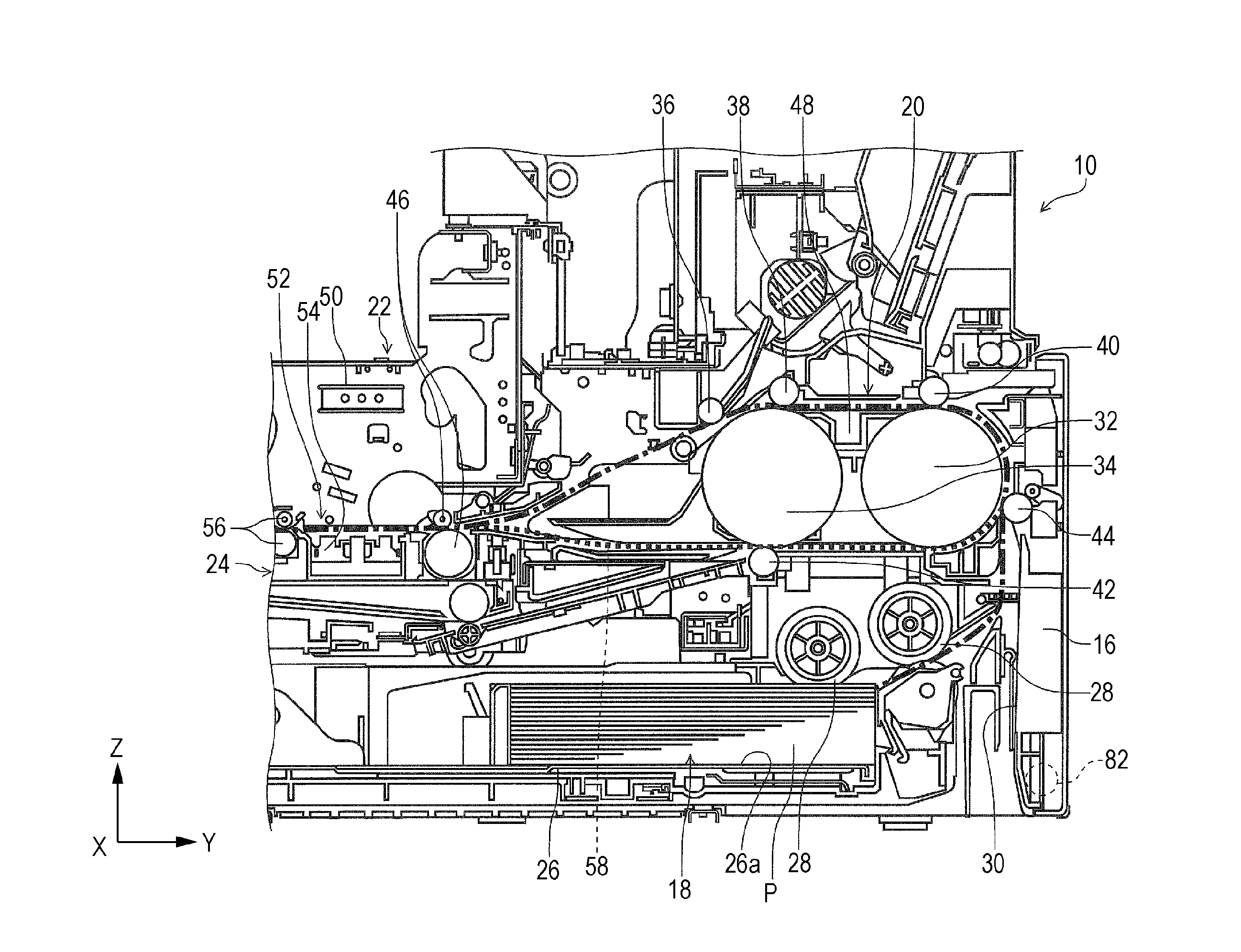
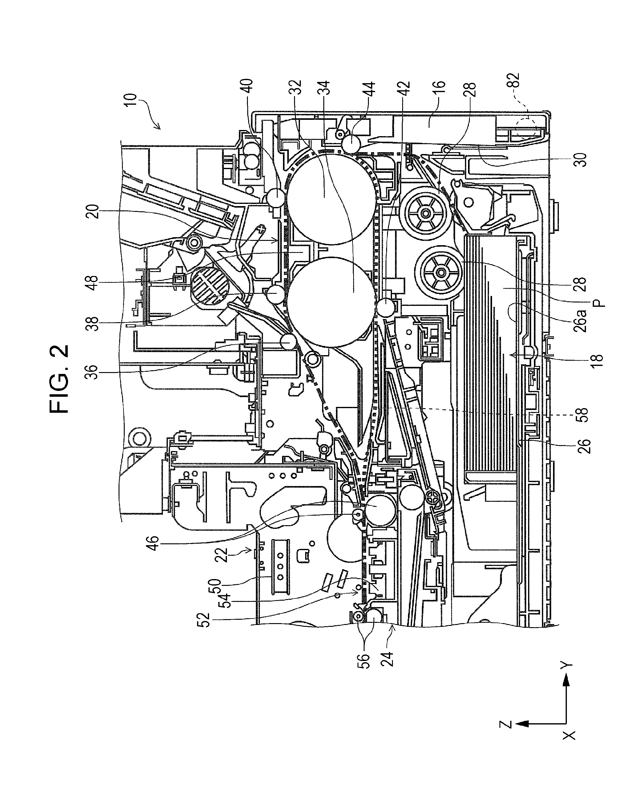
[0070]Next a detailed account of the transport unit 20 will be given with reference to FIG. 2. Additionally, the dashed-dotted line in FIG. 2 shows a medium transport pathway from the medium accommodation unit 18, and the broken line shows the reverse pathway 58 of the sheets P. The reverse roller 32 and the transport drive roller 34 are provided in positions that overlap with one another in the Z axis direction in FIG. 2. Therefore, it is possible to cut the dimensions of a disposition region of the reverse roller 32 and the transport drive roller 34 in the Z axis direction down to the bare minimum.

[0071]In addition, the reverse roller 32 and the transport drive roller 34 are disposed with an interval in the Y axis direction in FIG. 2. That is, in the transport pathway of the sheets P, the reverse roller 32 is positioned on the upstream side in the transport pathway, and the transport drive roller 34 is positioned on the downstream side in the transpo...

second example

[0121]A restricting unit 94 according to a second example of the invention will be described with reference to FIGS. 15A and 15B. The restricting unit 94 differs from the first example in that the restricting unit 94 is provided in a sliding member 96 that is capable of moving in a sliding manner in the Z axis direction in FIGS. 15A and 15B.

[0122]Upon referring to FIG. 15A, it is clear that the sliding member 96 is provided with the restricting unit 94 that is provided on a side of the sliding member 96 that opposes the rear surface cover 16, an elongated hole 98 that extends in the Z axis direction, a penetration hole 100 that penetrates the sliding member 96 in the Y axis direction, and an inclined portion 102 that is provided at a lower end portion of the sliding member 96, and is inclined on a side in the +Y direction.

[0123]In addition, a fixing pin 104 is provided in the device main body 12. The fixing pin 104 is inserted into the elongated hole 98. Therefore, the sliding membe...

modification examples of first example and second example

[0132](1) In the swinging member 72 in the first example and the sliding member 96 in the second example, the restricting units 68 and 94 are configured to change from the first state to the second state under their own weight, but in place of this configuration, the restricting units 68 and 94 may have configurations in which a biasing unit such as a spring, which biases toward a direction that changes from the first state to the second state, is provided in the swinging member 72 and the sliding member 96.

[0133]According to this configuration, since a biasing unit that biases from the first state to the second state are provided in the restricting units 68 and 94, it is possible to reliably change from the first state to the second state. As a result of this, it is possible to reliably retain the second state when the unit body 48 is in an uninstalled state with respect to the device main body 12, and it is possible to reliably restrict closing of the rear surface cover 16 in the ...


PUM


Abstract

A medium transport device includes a restricting unit that is provided in a device main body, and that is coupled with an attaching and detaching operation of a unit body, which configures a portion of a transport pathway, to the device main body. The restricting unit changes between a first state that allows the cover to attain a closed state with respect to the device main body and a second state that restricts the cover from attaining a closed state with respect to the device main body.

Description

BACKGROUND[0001]1. Technical Field[0002]The present invention relates to a medium transport device and recording device that are typical of facsimiles, printers, and the like.[0003]2. Related Art[0004]In recording devices of the related art that are typical of facsimiles, printers, and the like, when paper jams and transport faults occur in a transport pathway of a target recording medium, in order to clear a target recording medium that is jammed in the middle of a route of the transport pathway, clearing of the target recording medium that is jammed in the middle of the route of the transport pathway is performed by providing a cover that is openable and closeable with respect to the device main body, and exposing at least a portion of the transport pathway of the target recording medium by opening the cover with respect to the device main body.[0005]In such recording devices, for example, it is possible to unitize a portion of the transport pathway, and configure the portion of t...

Claims


Application Information

Patent Timeline
IPC IPC(8): B41J11/00B65H9/00B65H7/12B65H1/02
CPCB41J11/006B65H7/12B65H9/00B65H1/027B65H85/00B65H5/062B65H5/38B65H2402/46B65H2404/152B65H2404/1531B65H2404/6111B65H2511/417B65H2511/515B65H2601/11B65H2601/324B65H2402/10B65H2402/30B65H2402/32B65H2402/441B65H2402/45B65H2402/60B65H5/36B65H2402/31B65H2402/40B65H2402/44B65H2404/50B65H2404/60B65H2404/74G03G21/16G03G21/1623G03G21/1633G03G2215/00544G03G2221/1672G03G2221/1684G03G2221/1687G03G2221/169
Inventor AOKI, TAKESHIOKAMOTO, KATSUMI
Owner SEIKO EPSON CORP
Why Eureka
Try Eureka