
Optical apparatus

Inactive Publication Date: 2015-03-05
CANON KK
View PDF10 Cites 23 Cited by
  • Summary
  • Abstract
  • Description
  • Claims
  • Application Information

AI Technical Summary

Benefits of technology

The present invention is a small optical device that can efficiently dissipate heat. This makes it better than other similar products.

Problems solved by technology

However, a heating value of the image sensor generates tends to increase due to an increasing number of pixels, and a heat radiating measure becomes necessary.
The structure of Japanese Patent No. 4194221, in which a first lens unit optical system has the front lens is made of a large glass and hence is heavy, is disadvantageous for quick zooming and smooth moving-image capturing.
In addition, a smaller F-number leads to a larger optical system, and requires a large complicated drive mechanism.
It is difficult to mount the structure of Japanese Patent Laid-open No. 2010-56995 in a small camera, because the Peltier element and heat transfer structure are too complicated.

Method used


Image

  • Optical apparatus
  • Optical apparatus
  • Optical apparatus

Examples


Embodiment Construction

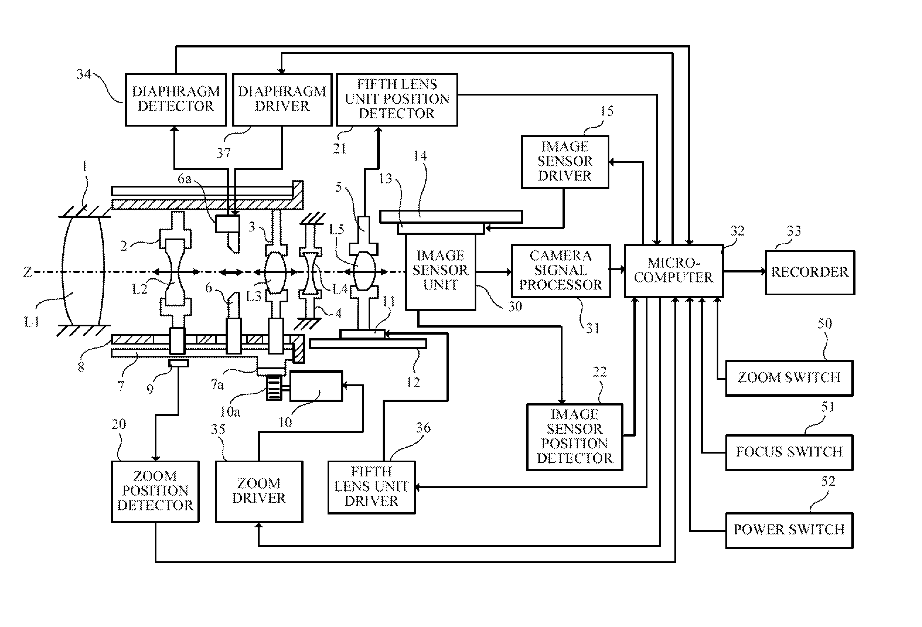
[0013]FIG. 1 is a block diagram of an image pickup apparatus (optical apparatus) according to this embodiment of the present invention. The image pickup apparatus is, for example, a lens integrated camera such as a digital video camera or a digital still camera, or a microscope. The left side in FIG. 1 is an object side.

[0014]In FIG. 1, reference numeral L1 denotes a fixed first lens unit (fixed unit) closest to the object side. Reference numerals L2 and L3 denote a second lens unit and a third lens unit, respectively, as magnification-varying lens units configured to move in an optical axis direction to vary the magnification. Reference numeral L4 denotes a fixed fourth lens unit, and reference numeral L5 denotes a fifth lens unit (focus lens) configured to move in the optical axis direction for focusing.

[0015]The first lens unit L1 to the fifth lens unit L5 constitute an image pickup optical system configured to form an optical image of an object. The image pickup optical system a...


PUM


Abstract

An optical apparatus includes a heat sink radiating the image sensor, a cooling fan unit configured to cool the heat sink, and a first lens barrel including a hollow portion configured to guide light to the image sensor. The first lens barrel holds the cooling fan unit and house the holder unit movably in the hollow portion in an optical axis direction of the image pickup optical system. The holder unit includes a first inlet and a first outlet. The first lens barrel includes a second inlet for taking in external air and a second outlet for exhausting the external air taken in through the second inlet. The first inlet is connected to the second inlet and the first outlet is connected to the second outlet when the holder unit is positioned in the hollow portion of the first lens barrel.

Description

BACKGROUND OF THE INVENTION[0001]1. Field of the Invention[0002]The present invention relates to an optical apparatus such as an image sensor unit, a lens barrel unit, a lens integrated camera, and a microscope.[0003]2. Description of the Related Art[0004]Recently, optical apparatuses such as a digital video camera and a digital still camera have been increasingly required to be downsized. For example, a so-called inner focus zoom type is smaller than a front focus type because a front lens and an image sensor are fixed while a magnification-varying unit and a focus unit are made movable in an optical axis direction inside a lens barrel. A retractable lens barrel is also smaller because the image sensor is fixed while the magnification-varying unit including the front lens is moved in the optical axis direction. However, a heating value of the image sensor generates tends to increase due to an increasing number of pixels, and a heat radiating measure becomes necessary.[0005]Japanese...

Claims


Application Information

Patent Timeline
IPC IPC(8): H04N5/225G02B21/36G02B7/04H04N5/33H04N5/232
CPCH04N5/2254H04N5/33G02B21/362H04N5/2252G02B7/04H04N5/23212G02B7/102H04N23/52H04N23/51H04N23/55H04N23/673H04N23/69
Inventor TSUZUKI, MASAHIKO
Owner CANON KK
Learn More