Constant force device, movement and mechanical timepiece
Active Publication Date: 2015-03-05
SEIKO INSTR INC
View PDF6 Cites 6 Cited by
Summary
Abstract
Description
Claims
Application Information
AI Technical Summary
This helps you quickly interpret patents by identifying the three key elements:
Problems solved by technology
Method used
Benefits of technology
Benefits of technology
The present patent aims to provide a device that can control the rotation of a stop wheel and pinion without losing power. This is useful for creating a constant force device, a movement, and even a mechanical timepiece.
Problems solved by technology
Consequently, there is a problem of an increasing loss of power for stopping or resuming the rotation of the stop wheel & pinion.
Method used
Image
Click on the blue label to locate the original text in one second.
Reading with bidirectional positioning of images and text.
Examples
first embodiment
[0055](Mechanical Timepiece)
[0056]Next, a first embodiment of this invention will be described with reference to FIGS. 1 to 11.
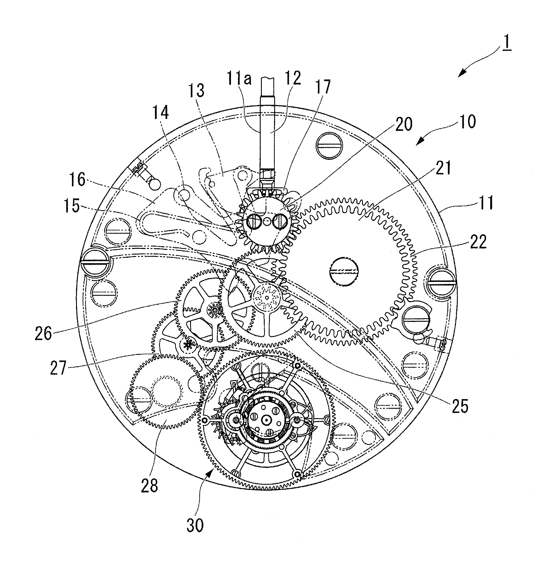
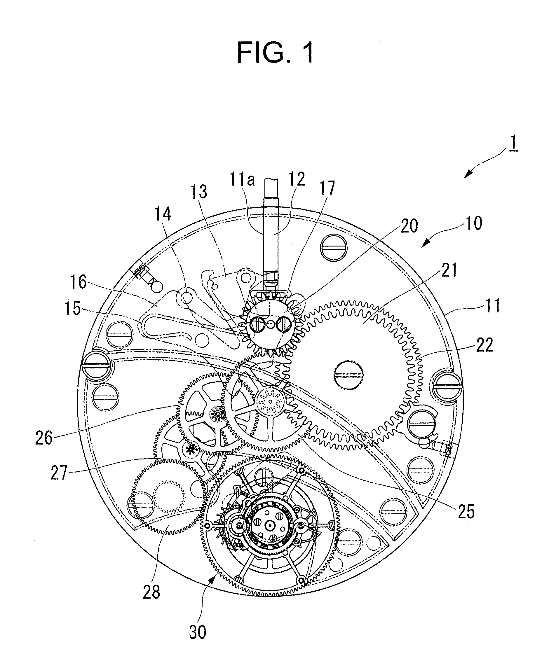
[0057]FIG. 1 is a plan view of a front side of a movement of a mechanical timepiece 1.
[0058]As illustrated in the drawing, the mechanical timepiece is configured to have a movement 10 and a case (not illustrated) for accommodating the movement 10.
[0059]The movement 10 has a main plate 11 configuring a substrate. A dial (not illustrated) is arranged in a rear side of the main plate 11. A train wheel incorporated in a front side of the movement 10 is referred to as a front train wheel, and a train wheel incorporated in a rear side of the movement 10 is referred to as a rear train wheel.
[0060]A winding stem guide hole 11a is formed in the main plate 11 and a winding stem 12 is rotatably incorporated therein. The winding stem 12 has an axially determined position by a switching device having a setting lever 13, a yoke 14, a yoke spring 15, and a setting lever ju...
first modification example of first embodiment
[0177]Next, referring to FIGS. 12 and 13, a first modification example of the first embodiment will be described.
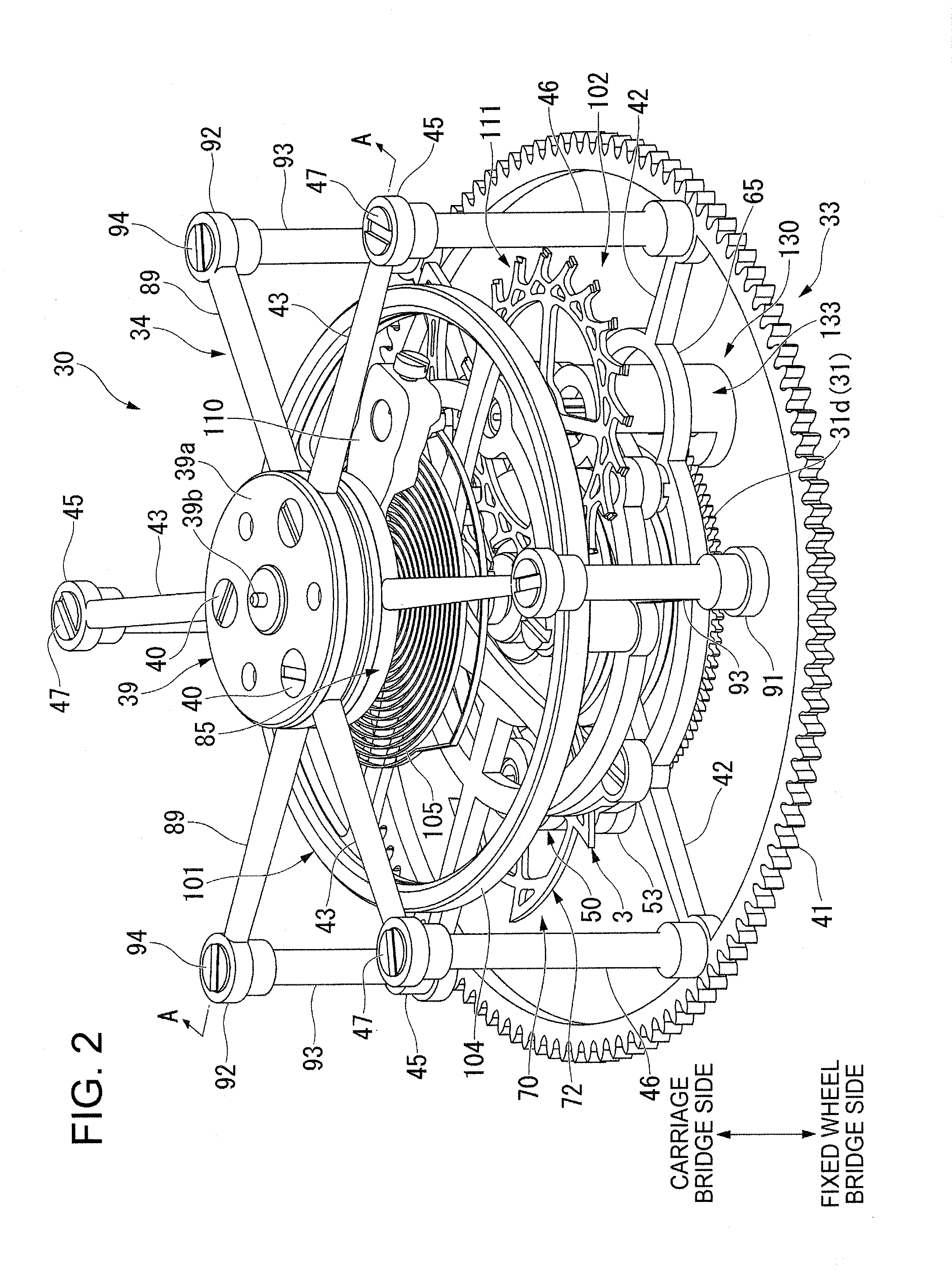
[0178]FIG. 12 is a perspective view when a portion of the inner carriage 34 and the stop wheel & pinion 70 disposed in the outer carriage 33 according to the first modification example of the first embodiment is viewed from the fixed wheel bridge 29 side, and FIG. 13 is a perspective view of a stopper 196 according to the first modification example of the first embodiment. The same reference numerals are given to elements which are the same as those in the above-described first embodiment, and description thereof will be omitted (in the following description, the same also applied to each modification example of the first embodiment, second embodiment, and a modification example of a second embodiment).
[0179]As illustrated in FIGS. 12 and 13, a different point between the first embodiment and the first modification example of the first embodiment is that a shape of the st...
second modification example of first embodiment
[0188]Next, referring to FIGS. 14 to 16, a second modification example of the first embodiment will be described.
[0189]FIG. 14 is a perspective view when a portion of the outer carriage 33 and a portion of the inner carriage 34 according to the second modification example of the first embodiment are viewed from the fixed wheel bridge 29 side.
[0190]As illustrated in the drawing, a different point between the first embodiment and the second modification example of the first embodiment is that only the second modification example is provided with the phase shift regulation mechanism 160 which controls the phase shift between the outer carriage and the inner carriage 34 so as to fall within a predetermined angle range.
[0191]The phase shift regulation mechanism 160 includes a regulation ring 161 which is integrally molded in the support bar 48 of the outer carriage 33, and an eccentric pin 162 which is disposed in the support bar 95 of the inner carriage 34 and is inserted into the regul...
PUM
Abstract
There are provided a constant force device, a movement, and a mechanical timepiece which can decrease a loss of power for controlling rotation of a stop wheel & pinion. A constant force device includes an inner carriage that outputs an output torque by being rotated around a tenon of a first inner rotation body and a tenon of a second inner rotation body, a constant force spring that supplies a rotation force to the inner carriage, an outer carriage that stores a resilient force in the constant force spring by being rotated around a tenon of a first outer rotation body and a tenon of a second outer rotation body, a stop wheel & pinion that is supported to be rotatable around a stop wheel axle body in the outer carriage, and that is rotatable around the tenon of the first outer rotation body and the tenon of the second outer rotation body, and a stopper that is rotated around the tenon of the first inner rotation body and the tenon of the second inner rotation body together with the inner carriage, and that engages with the stop wheel & pinion in response to rotation of the stop wheel & pinion which is rotated around the stop wheel axle body.
Description
BACKGROUND OF THE INVENTION[0001]1. Field of the Invention[0002]This invention relates to a constant force device, a movement and a mechanical timepiece.[0003]2. Description of the Related Art[0004]In a mechanical timepiece, if a rotation torque transmitted to an escape wheel & pinion of an escapement from a barrel drum varies in response to unwinding of a main spring in the barrel drum, an oscillation angle of a balance with hairspring is changed and a rate of a timepiece is changed. Therefore, in order to suppress the variation in the rotation torque transmitted to the escape wheel & pinion, a constant force device is proposed in which a constant force spring (pre-tensioning spiral spring) is arranged between the barrel drum and the escapement.[0005]For example, as the constant force device, those which include a stop wheel & pinion having a stop pinion (stop wheel pinion), an escape wheel & pinion having an escape pinion (escape wheel shaft), a tensioning ring attached to a tensi...
Claims
Application Information
Patent Timeline
Application Date:The date an application was filed.
Publication Date:The date a patent or application was officially published.
First Publication Date:The earliest publication date of a patent with the same application number.
Issue Date:Publication date of the patent grant document.
PCT Entry Date:The Entry date of PCT National Phase.
Estimated Expiry Date:The statutory expiry date of a patent right according to the Patent Law, and it is the longest term of protection that the patent right can achieve without the termination of the patent right due to other reasons(Term extension factor has been taken into account ).
Invalid Date:Actual expiry date is based on effective date or publication date of legal transaction data of invalid patent.

