Circuit integrating a tunable antenna with a standing wave rate correction

Active Publication Date: 2010-01-28
STMICROELECTRONICS (TOURS) SAS
View PDF21 Cites 25 Cited by
  • Summary
  • Abstract
  • Description
  • Claims
  • Application Information

AI Technical Summary

Benefits of technology

[0014]It would also be desirable to have a transceiver circuit in which line losses are decreased.

Problems solved by technology

A problem which is particularly critical for high frequencies is that the system environment has a direct influence upon the impedance of the antenna.
As a result, even for an antenna having good nominal characteristics in terms of ratio of the transmitted power to the reflected power (RL—Return Loss), this ratio may be disturbed by the environment, for example, when a user's hand comes close to the antenna.
Further, the presence of a matching circuit adds losses in the transmission chain by the capacitive and inductive elements in series between the output of transmit head 1 and antenna 3.

Method used


Image

  • Circuit integrating a tunable antenna with a standing wave rate correction
  • Circuit integrating a tunable antenna with a standing wave rate correction
  • Circuit integrating a tunable antenna with a standing wave rate correction

Examples


Embodiment Construction

[0035]The same elements have been designated with the same reference numerals in the different drawings.

[0036]For clarity, only those elements which are useful to the understanding of the present invention have been shown and will be described. In particular, the circuits for generating the signals to be transmitted and processing the received signals have not been detailed, the present invention being compatible with usual circuits.

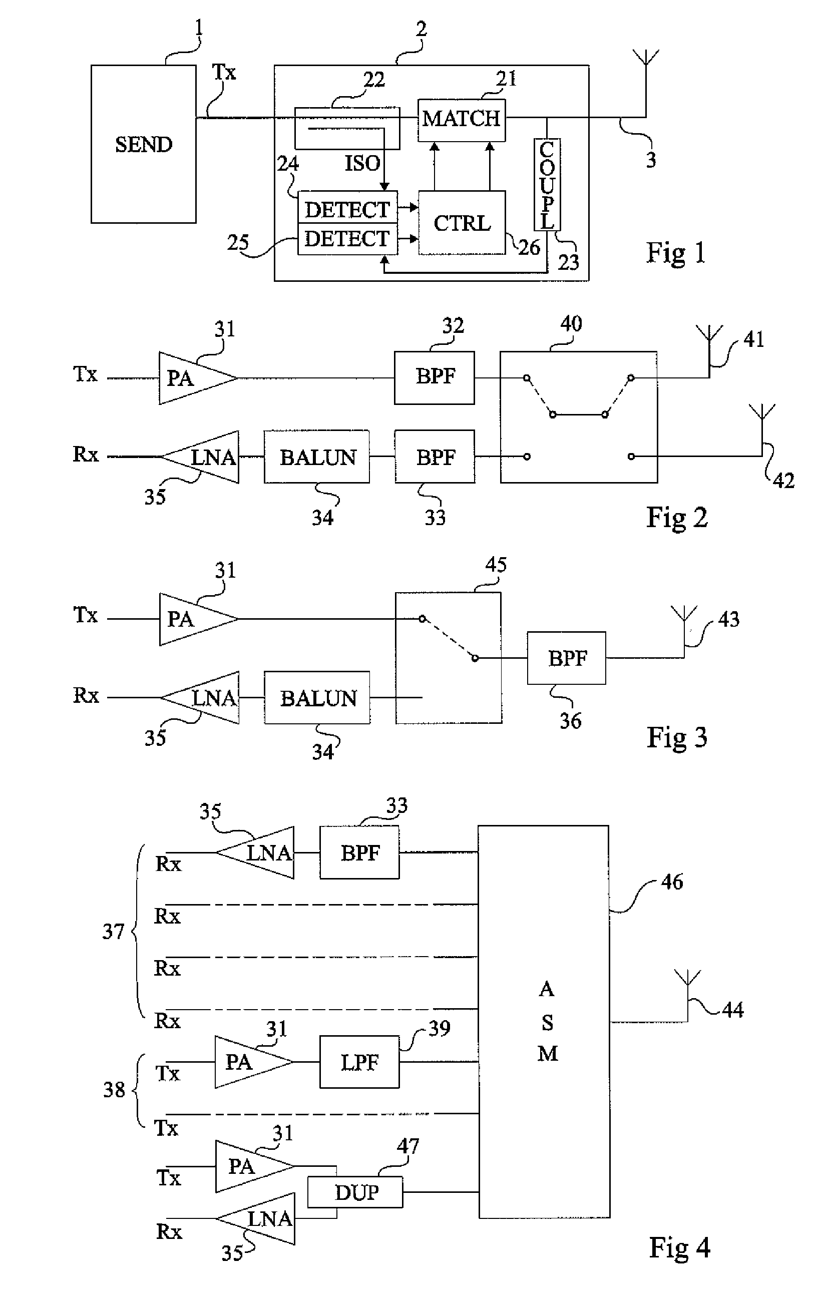
[0037]FIG. 2 is a block diagram of an example of a radio-frequency transceiver chain of the type to which the present invention applies.

[0038]On the transmit side, a signal Tx to be transmitted proceeds through an amplifier 31 (PA) before being processed by a band-pass filter 32 (BPF) for transmission by an antenna 41 or 42. A so-called diversified switch 40 is in charge of routing the signal to be transmitted from filter 32 to antenna 41 or 42. On the receive side, switch 40 routes a received signal from antenna 41 or 42 to a band-pass filter 33. Filter...


PUM


Abstract

An integrated electronic radio-frequency transceiver circuit, including: at least one terminal intended to receive a signal to be transmitted or to transmit a received signal; at least one planar antenna, with a settable resonance frequency; at least one bidirectional coupler having a primary line interposed between the terminal and the antenna and having the respective terminals of a secondary line providing data representative of the transmitted power and of the power reflected on the primary line side; at least one detector of the transmitted power and of the reflected power; and a circuit for selecting the resonance frequency of the antenna according to the ratio between the transmitted power and the reflected power.

Description

CROSS REFERENCE TO RELATED APPLICATIONS[0001]This application claims the priority benefit of French patent application number 08 / 51486, filed on Mar. 7, 2008, entitled “CIRCUIT INTEGRATING A TUNABLE ANTENNA WITH A STANDING WAVE RATE CORRECTION,” which is hereby incorporated by reference to the maximum extent allowable by law.BACKGROUND OF THE INVENTION[0002]1. Field of the Invention[0003]The present invention relates generally to electronic circuits and, more specifically, to radio-frequency transceiver circuits, intended for very high frequencies (greater than 100 MHz).[0004]2. Discussion of the Related Art[0005]A problem which is particularly critical for high frequencies is that the system environment has a direct influence upon the impedance of the antenna. As a result, even for an antenna having good nominal characteristics in terms of ratio of the transmitted power to the reflected power (RL—Return Loss), this ratio may be disturbed by the environment, for example, when a user...

Claims


Application Information

Patent Timeline
IPC IPC(8): H04B1/40
CPCH01Q1/241H01Q1/36H01Q13/103H01Q9/145H01Q9/0442
Inventor BONNET, BENO TDUPONT, FRANCOIS
Owner STMICROELECTRONICS (TOURS) SAS
Why Eureka
Try Eureka