Terminal structure of direct electric current multilayer structure superconducting cable and DC superconducting cable line

Inactive Publication Date: 2006-01-24
SUMITOMO ELECTRIC IND LTD
View PDF22 Cites 25 Cited by
  • Summary
  • Abstract
  • Description
  • Claims
  • Application Information

AI Technical Summary

Benefits of technology

[0006]An object of the present invention is to provide a terminal structure of a direct electric current superconducting cable and a direct electric current superconducting cable line, in which a single superconducting cable is made possible to transmit electric power of a plurality of circuits so that the transmission of increased electric current, the minimization of needed space, and the decrease of transmission loss can be achieved.
[0013]Also, layer-insulations provided in the superconducting cable may be afforded with the dielectric strength that enables the voltage of other superconducting layers to be maintained when any layer of the superconducting multiple layers is grounded.

Problems solved by technology

However, a number of cables must be used according to the number of the power supplies, and the space for arranging the cable distribution line is necessary.

Method used


Image

  • Terminal structure of direct electric current multilayer structure superconducting cable and DC superconducting cable line
  • Terminal structure of direct electric current multilayer structure superconducting cable and DC superconducting cable line
  • Terminal structure of direct electric current multilayer structure superconducting cable and DC superconducting cable line

Examples


first embodiment

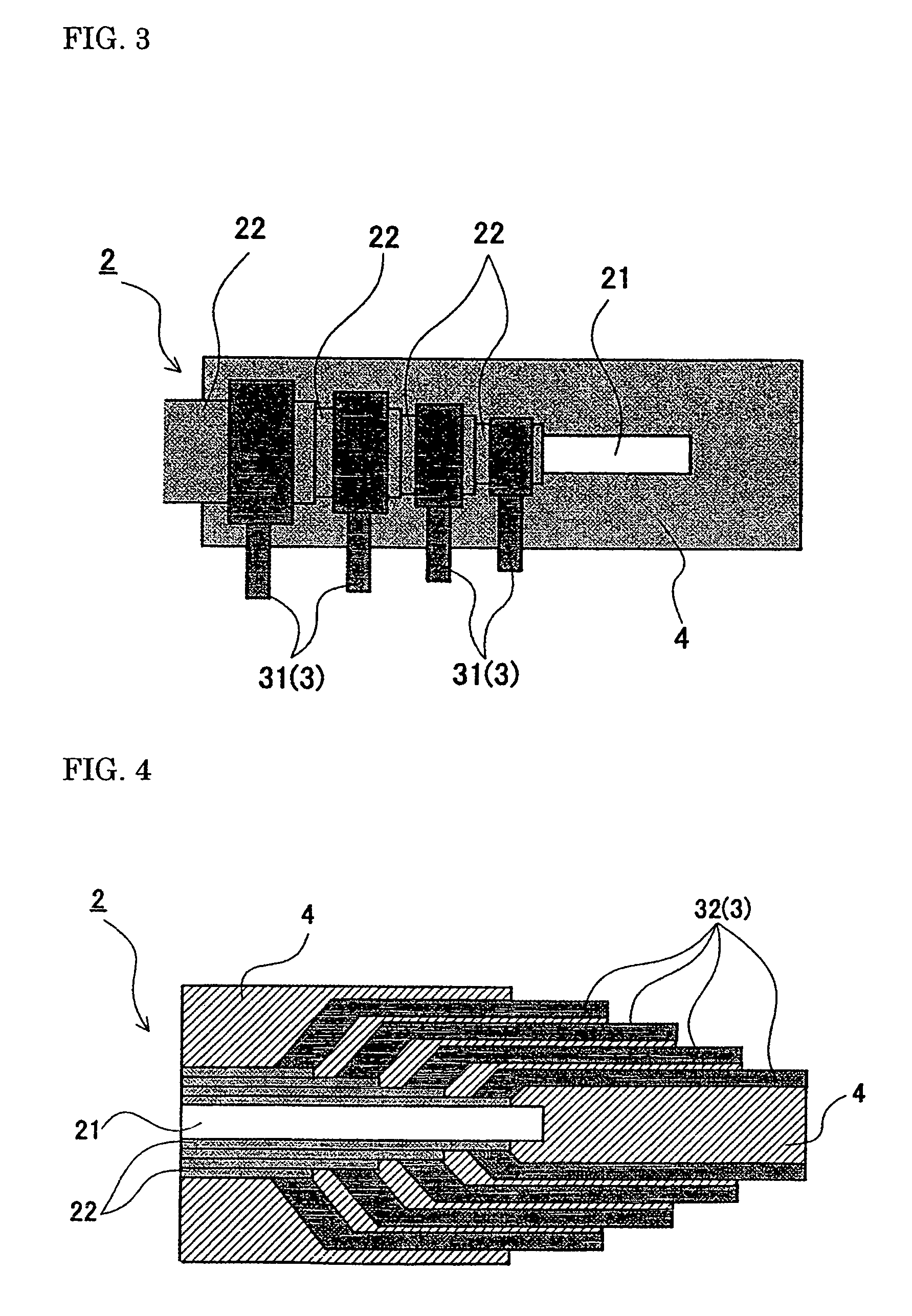
[0036]In the first embodiment shown in FIG. 3, a plurality of outgoing conductors 31 (3) are formed, and an end of each outgoing conductor 31 is connected individually with the exposed end of a corresponding superconducting layer 22. Then, the other end portion of each outgoing conductor is extended from the exposed portion of the respective superconducting layers 22 at a right angle relative to an axial direction of the superconducting cable. In this case, the respective outgoing conductors 31 are extended in parallel as shown in FIG. 3.

second embodiment

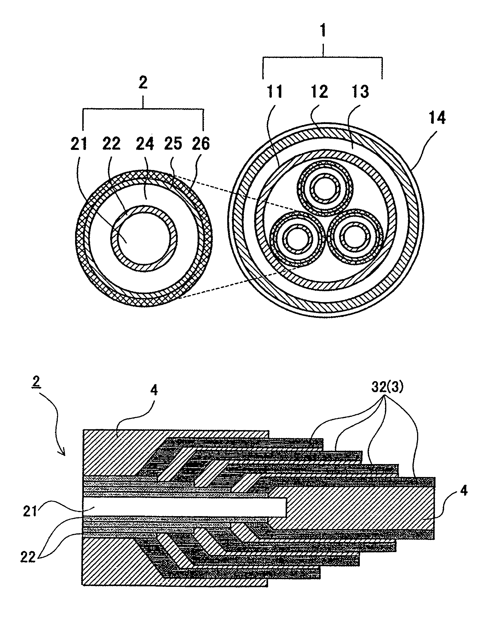
[0037]The outgoing conductors 32 (3) of the second embodiment shown in FIG. 4 are composed of a plurality of outgoing conductors 32 each having a tubular shape (or a tubular shape divided in half circle) of a different dimension. An end of the outgoing conductors 32 are connected with the exposed end portion of the corresponding superconducting layers 22 in a manner such that the tubular bodies are disposed concentrically one over the other. Then, the other end of the outgoing conductors 32 are extended along the axial direction of the cable. The outgoing conductors 32 are connected with the exposed portion of the superconducting layers 22 such that an inner superconducting layer is connected with an outgoing conductor having a smaller diameter step by step in the order of a smaller one to a larger one.

[0038]For extending the outgoing conductors along the axial direction of the superconducting cable, an end of the outgoing conductor made of wires instead of a tubular body may be ind...


PUM


Abstract

The present invention discloses a direct electric current superconducting cable having a core and a plurality of superconducting layers provided over the core with end portions of the superconducting layers exposed in a step-by-step manner from an outer layer to an inner layer and connected individually to outgoing conductors. The superconducting layers are insulated from each other. An insulating fixing member is used to support the core and the outgoing conductors. An electrical insulation layer, a return-current conductor layer and an insulating protective layer in that order surrounds the outermost superconducting layer.

Description

BACKGROUND OF THE INVENTION[0001]1. Field of the Invention[0002]The present invention relates to the terminal structure of a direct electric current (DC) superconducting cable and to a DC superconducting cable line.[0003]2. Description of the Related Art[0004]The superconductor of a superconducting cable is generally constituted by a superconducting layer which is formed by spirally winding superconducting wires around a core material (hereinafter called a “former”). When the superconducting cable is used as a direct electric current cable, soldering is generally performed for connecting superconductors together or connecting the end of a superconductor with a wire consisting of a normal conductor (for example, refer to Japanese Patent Application Publication No. 10-228933). Some of superconducting cables have a multilayer structure superconductor consisting of a plurality of superconducting layers (for example, see FIG. 3 of Japanese Patent Application Publication No. 10-228933). I...

Claims


Application Information

Patent Timeline
IPC IPC(8): H01R24/04H01R4/66H01R13/648H01B13/00H01B12/02H01R4/68H01R24/58H02G1/14H02G15/04
CPCH01R4/68H02G15/34Y02E40/648Y02E40/60H01B12/02
Inventor HIROSE, MASAYUKI
Owner SUMITOMO ELECTRIC IND LTD
Why Eureka
Try Eureka