Rolling bearing and power transmission device including rolling bearing

a technology of rolling bearing and power transmission device, which is applied in the direction of roller bearings, mechanical equipment, rotary machine parts, etc., can solve the problems of increasing costs reduce the viscosity of lubricant, and reduce the torque

Inactive Publication Date: 2015-03-05
JTEKT CORP
View PDF1 Cites 4 Cited by
  • Summary
  • Abstract
  • Description
  • Claims
  • Application Information

AI Technical Summary

Benefits of technology

[0007]The present invention provides a rolling bearing in which bubbles are generated in lubricant to decrease a viscous resistance of the lubricant without the necessity of disposing a dedicated bubble generating device, and a power transmission device including the rolling bearing.

Problems solved by technology

However, in the rolling bearing described in JP 2008-82547 A, a dedicated bubble generating device for mixing bubbles into the lubricant and supplying them to the rolling bearing should be disposed outside the rolling bearing, which increases cost and also causes necessity to secure a space in which to dispose the bubble generating device.

Method used


Image

  • Rolling bearing and power transmission device including rolling bearing
  • Rolling bearing and power transmission device including rolling bearing
  • Rolling bearing and power transmission device including rolling bearing

Examples


first embodiment

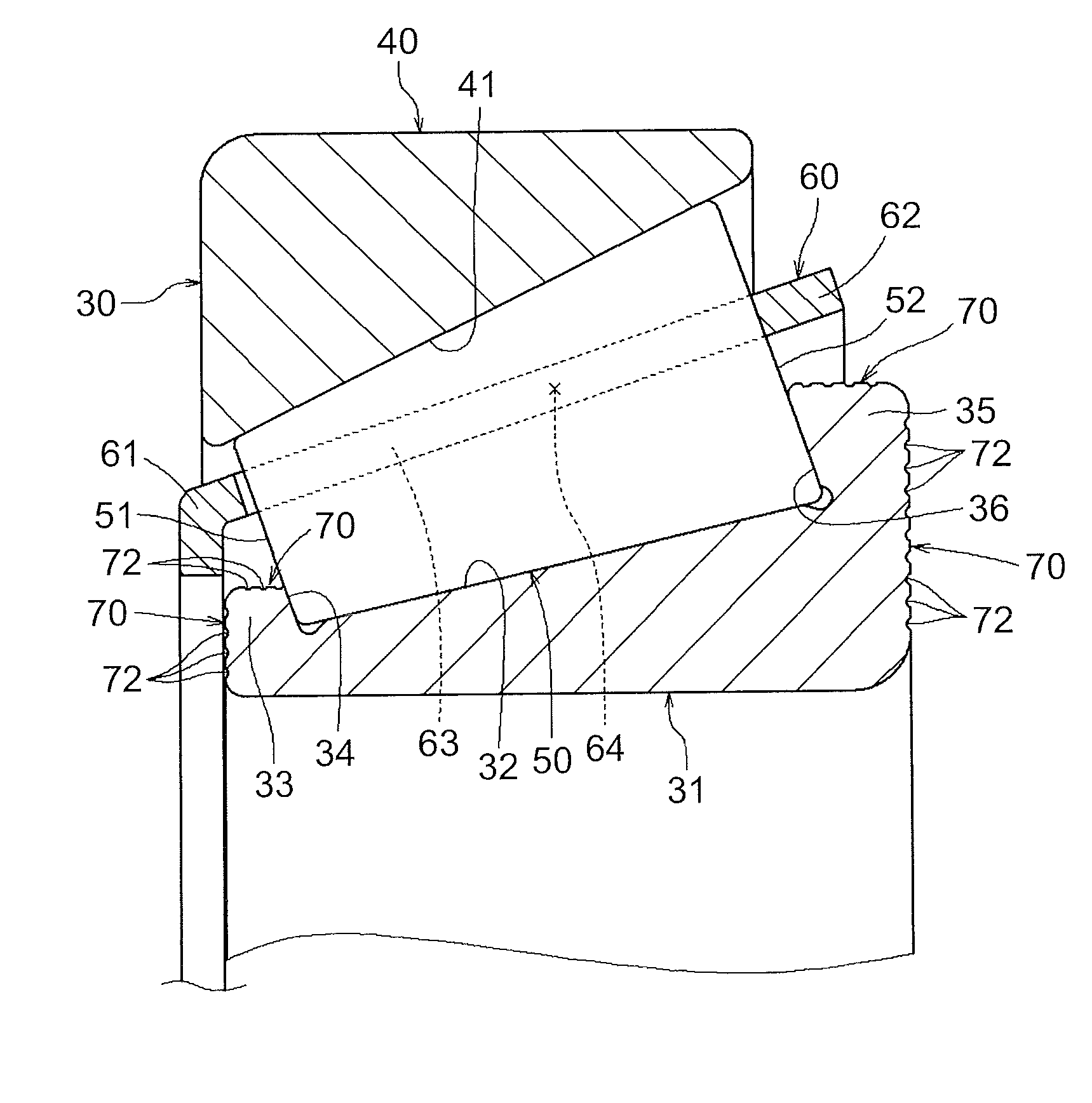
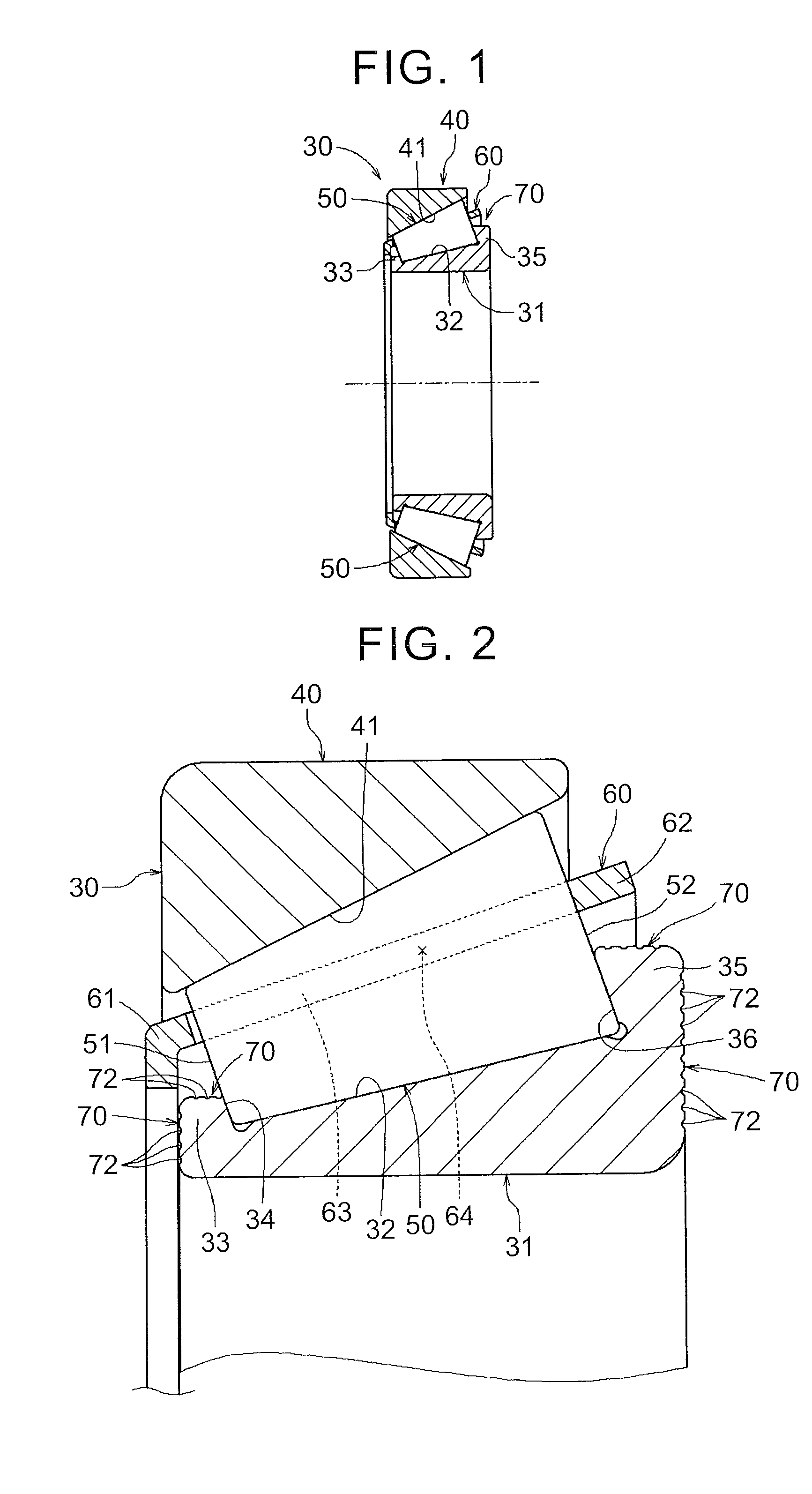
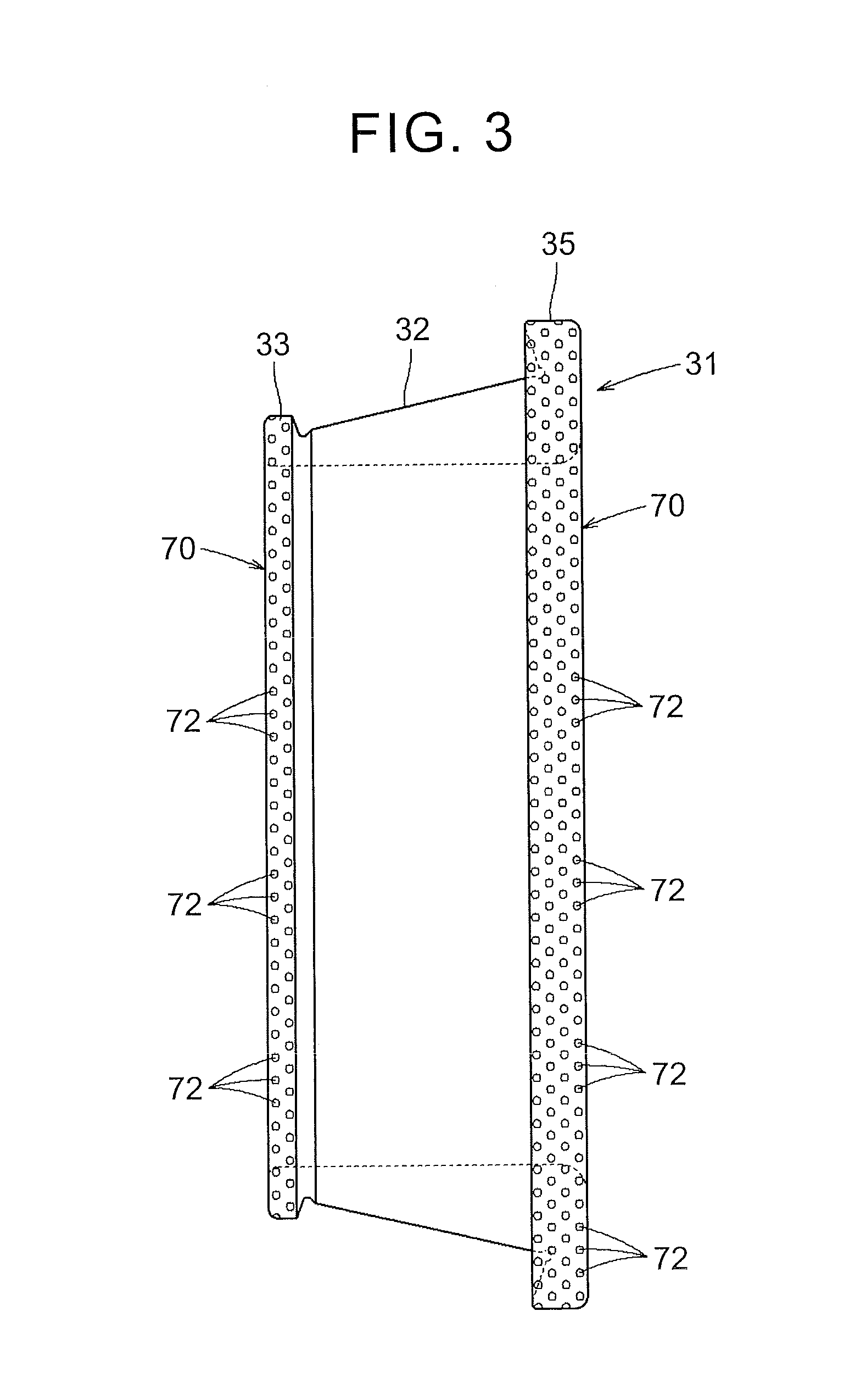
[0048]the present invention is described with reference to FIGS. 1 to 3. As illustrated in FIGS. 1, 2, a tapered roller bearing 30 as a rolling bearing includes an inner ring 31, an outer ring 40, a plurality of tapered rollers 50, and a cage 60. The inner ring 31 is formed in a tubular shape so as to have a central hole, and an inner-ring raceway surface 32 having a tapered shaft shape in which a diameter is gradually increased from one end toward the other end is formed on an outer peripheral surface of the inner ring 31. Further, on an outer peripheral surface of one end of the inner ring 31 (a small-diameter side of the inner-ring raceway surface 32), a small rib portion 33 having a guideway 34 that guides small end faces 51 of the tapered rollers 50 is formed, and on an outer peripheral surface of the other end (a large-diameter side of the inner-ring raceway surface 32), a large rib portion 35 having a guideway 36 that guides large end faces 52 of the tapered rollers 50 is for...

second embodiment

[0063]the present invention is described with reference to FIGS. 8 to 12. As illustrated in FIGS. 8, 9, a tapered roller bearing 30 as a rolling bearing includes an inner ring 31, an outer ring 40, a plurality of tapered rollers 50, and a cage 60. The inner ring 31 is formed in a tubular shape having a central hole, and an inner-ring raceway surface 32 having a tapered shaft shape in which a diameter is gradually increased from one end toward the other end is formed on an outer peripheral surface of the inner ring 31. Further, on an outer peripheral surface of one end of the inner ring 31 (a small-diameter side of the inner-ring raceway surface 32), a small rib portion 33 having a guideway 34 that guides small end faces 51 of the tapered rollers 50 is formed, and on an outer peripheral surface of the other end (a large-diameter side of the inner-ring raceway surface 32), a large rib portion 35 having a guideway 36 that guides large end faces 52 of the tapered rollers 50 is formed.

[0...


PUM


Abstract

A rolling bearing includes an inner ring; an outer ring coaxially disposed around an outer peripheral surface of the inner ring with an annular space between the inner ring and the outer ring; a plurality of rolling elements rollably disposed in the annular space; a cage that retains the rolling elements; and a bubble generating mechanism that generates bubbles in liquid lubricant during bearing rotation, wherein the liquid lubricant flows through the annular space.

Description

INCORPORATION BY REFERENCE[0001]The disclosure of Japanese Patent Applications No. 2013-176529 and 2013-176532 filed on Aug. 28, 2013 including the specification, drawings and abstract is incorporated herein by reference in its entirety.BACKGROUND OF THE INVENTION[0002]1. Field of the Invention[0003]The present invention relates to a rolling bearing and a power transmission device including the rolling bearing.[0004]2. Description of Related Art[0005]In order to achieve torque reduction by reducing a viscous resistance of lubricant, there is a conventional rolling bearing as described in Japanese Patent Application Publication No. 2008-82547 (JP 2008-82547 A), for example. In the rolling bearing, a bubble generating device (a microbubble generator) is disposed outside the rolling bearing so that bubbles generated by the bubble generating device are mixed into lubricant, and then supplied to the rolling bearing. Thus, a viscous resistance of the lubricant is reduced.[0006]However, in...

Claims


Application Information

Patent Timeline
Patent Type & Authority Applications(United States)
IPC IPC(8): F16C33/46F16C19/36
CPCF16C19/364F16C33/46F16C2240/44F16C33/6651F16C33/6681F16C19/548F16C33/4623F16C2210/04F16C33/583F16C2361/61
Inventor MURATA, JUNJIKAMAMOTO, SHIGEO
Owner JTEKT CORP
Why Eureka
Try Eureka