Preparation method for microfluidic array controller

An array controller and microfluidic technology, applied in chemical instruments and methods, laboratory utensils, laboratory containers, etc., can solve the problem of difficult to achieve large-scale fluid array control, reduce the number of leads and meet the needs of use , the effect of control voltage reduction

Active Publication Date: 2018-12-11
BEIJING MECHANICAL EQUIP INST
View PDF9 Cites 2 Cited by
  • Summary
  • Abstract
  • Description
  • Claims
  • Application Information

AI Technical Summary

Problems solved by technology

[0006] In view of the above analysis, the embodiment of the present invention aims to provide a method for preparing a microfluidic array controller to solve the problem that it is difficult to realize large-scale fluidic array control in the prior art

Method used


Image

  • Preparation method for microfluidic array controller
  • Preparation method for microfluidic array controller
  • Preparation method for microfluidic array controller

Examples


Embodiment 1

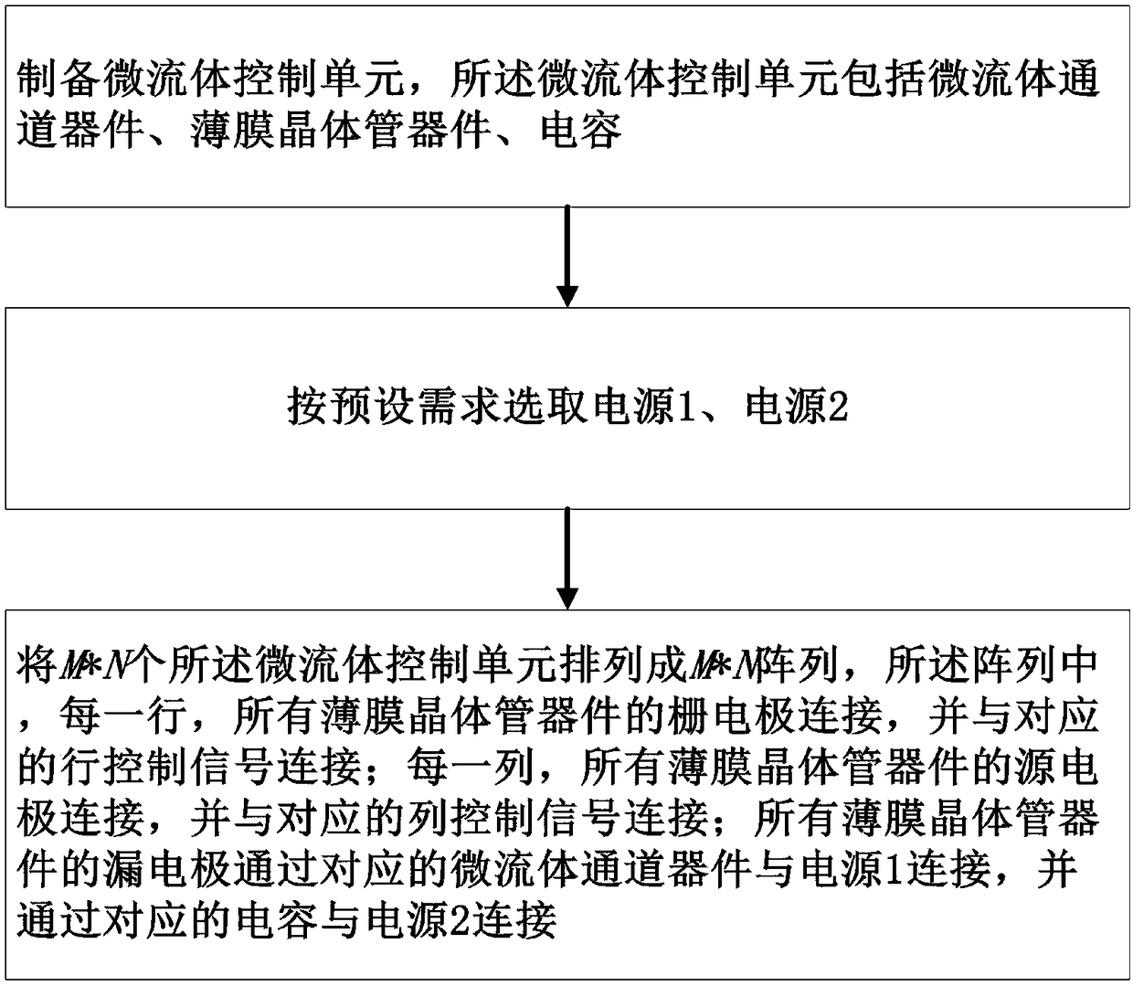
[0071] Such as figure 2 As shown, a specific embodiment of the present invention discloses a method for preparing a microfluidic array controller, comprising the following steps:

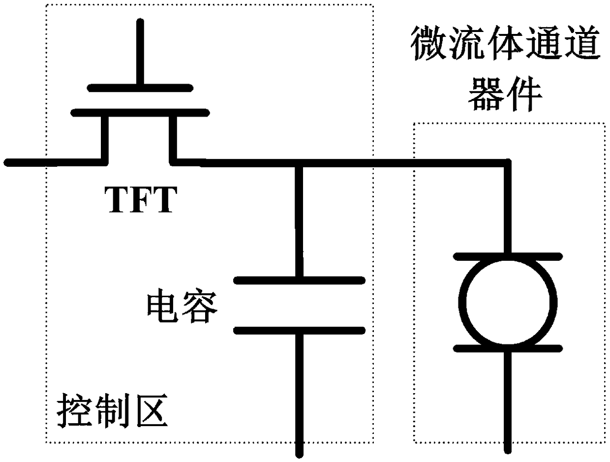
[0072] S1. Prepare a microfluidic control unit, the microfluidic control unit includes a microfluidic channel device, a thin film transistor device, and a capacitor.

[0073] S2. Select power supply 1 and power supply 2 according to preset requirements.

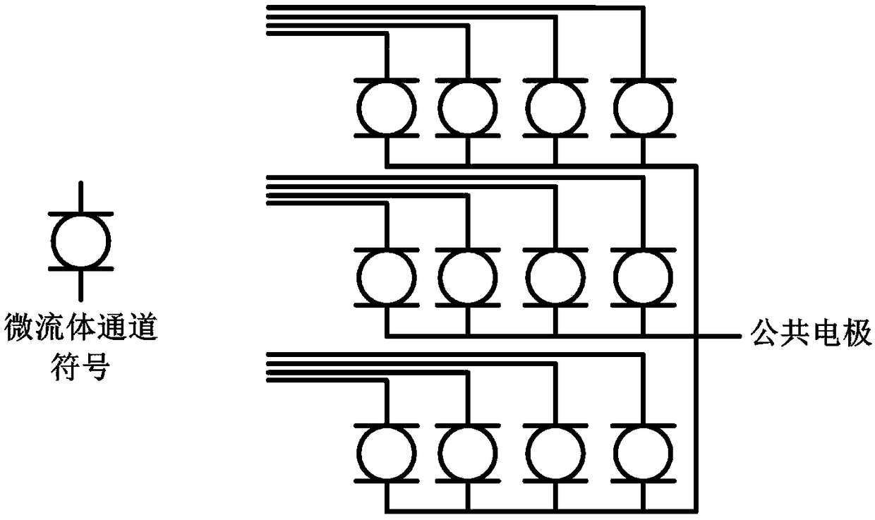
[0074] S3. Arranging M×N microfluidic control units into an M×N array, in the array, in each row, the gate electrodes of all thin film transistor devices are connected, and are connected to the corresponding row control signals; in each column, all The source electrodes of the thin film transistor devices are connected to the corresponding column control signals; the drain electrodes of all the thin film transistor devices are connected to the power source 1 through the corresponding microfluidic channel devices, and connected to the power source...

Embodiment 2

[0081] Such as Figure 5 As shown, optimization is carried out on the basis of the foregoing examples, and the steps of preparing the microfluidic control unit include:

[0082] S11. Prepare the control layer of the microfluidic control unit on the silicon wafer or the first glass substrate, and the control layer includes thin film transistor devices and capacitors.

[0083] S12. Prepare a passivation layer on the control layer, and make through holes at preset positions on the passivation layer. The process of preparing the passivation layer is chemical vapor deposition or physical vapor deposition, and the material used is at least one of silicon oxide, hafnium oxide, aluminum oxide, titanium oxide, silicon nitride, and parylene, with a thickness of 100nm to 2μm . The process of making via holes on the passivation layer is photolithography and etching process. The preset position of the through hole is above the drain electrode of the thin film transistor.

[0084] S13. ...


PUM


Abstract

The invention relates to a preparation method for a microfluidic array controller, and belongs to the technical field of microfluidic control. The preparation method solves the problem that large-scale microfluidic array control is not easy to realize in the prior art. The preparation method comprises the following steps that microfluidic control units are prepared, wherein each microfluidic control unit comprises a microfluidic channel device, a thin-film transistor device and a capacitor; a power supply 1 and a power supply 2 are selected according to the preset requirement; and M*N microfluidic control units are arranged into a M*N array and are connected in a line connection mode. According to the preparation method, the prepared M*N array only needs M+N+2 leads, and the microfluidic control voltage only needs to be about 20 V. The preparation method for the microfluidic array controller has the advantages that the large-scale microfluidic arrays control can be realized, the large-scale microfluidic array control difficulty can be greatly lowered, the number of the leads can be decreased, and a novel technological approach is provided for the practicability of a microfluidic control chip.

Description

technical field [0001] The invention relates to the technical field of microfluidic control, in particular to a preparation method of a microfluidic array controller. Background technique [0002] Microfluidic control is a control technology that uses voltage signals to control the movement, segmentation, and fusion of pigment droplets. It is one of the core technologies for realizing micro-electrochemical, chemical, medical and biochips. [0003] Microfluidic controllers prepared by existing methods generally use arrayed control electrodes to achieve microfluidic control. However, the existing microfluidic controllers are limited by the number of interconnection leads, and the scale of the electrode array is far from meeting the requirements of use, which seriously hinders the popularization and application of microfluidic control chips. [0004] The structure of the microfluidic array controller prepared by the existing method is as follows: figure 1 As shown, if the siz...

Claims


Application Information

Patent Timeline
Patent Type & Authority Applications(China)
IPC IPC(8): B01L3/00
CPCB01L3/502707B01L3/502715
Inventor 刘立滨许诺臧金良李平刘宇航
Owner BEIJING MECHANICAL EQUIP INST
Why Eureka
Try Eureka