Clock and data recovery circuit

a clock and data recovery technology, applied in the field of communication science and technology, can solve the problems of low power consumption, high input swing, and inferior locking time and jitter tolerance of linear cdrs, and achieve the effects of improving input sensitivity, jitter performance and locking characteristics

Active Publication Date: 2015-06-25
FUDAN UNIV
View PDF0 Cites 2 Cited by
  • Summary
  • Abstract
  • Description
  • Claims
  • Application Information

AI Technical Summary

Benefits of technology

[0005]This invention proposes a novel CDR circuit with improved i

Problems solved by technology

However, its high supple voltage decides its low-grade performance in power consumption.
While linear CDRs exhibit excellent recovered clock jitter due to the lower quantization jitter, the input data is supposed to drive the logic circuits directly, which demands high input swing.
Besides, the locking time and jitter toleranc

Method used


Image

  • Clock and data recovery circuit
  • Clock and data recovery circuit
  • Clock and data recovery circuit

Examples


Embodiment Construction

[0036]The following contents further illustrate the detailed implementation of present invention in combination with attached drawings and detailed description of the embodiments.

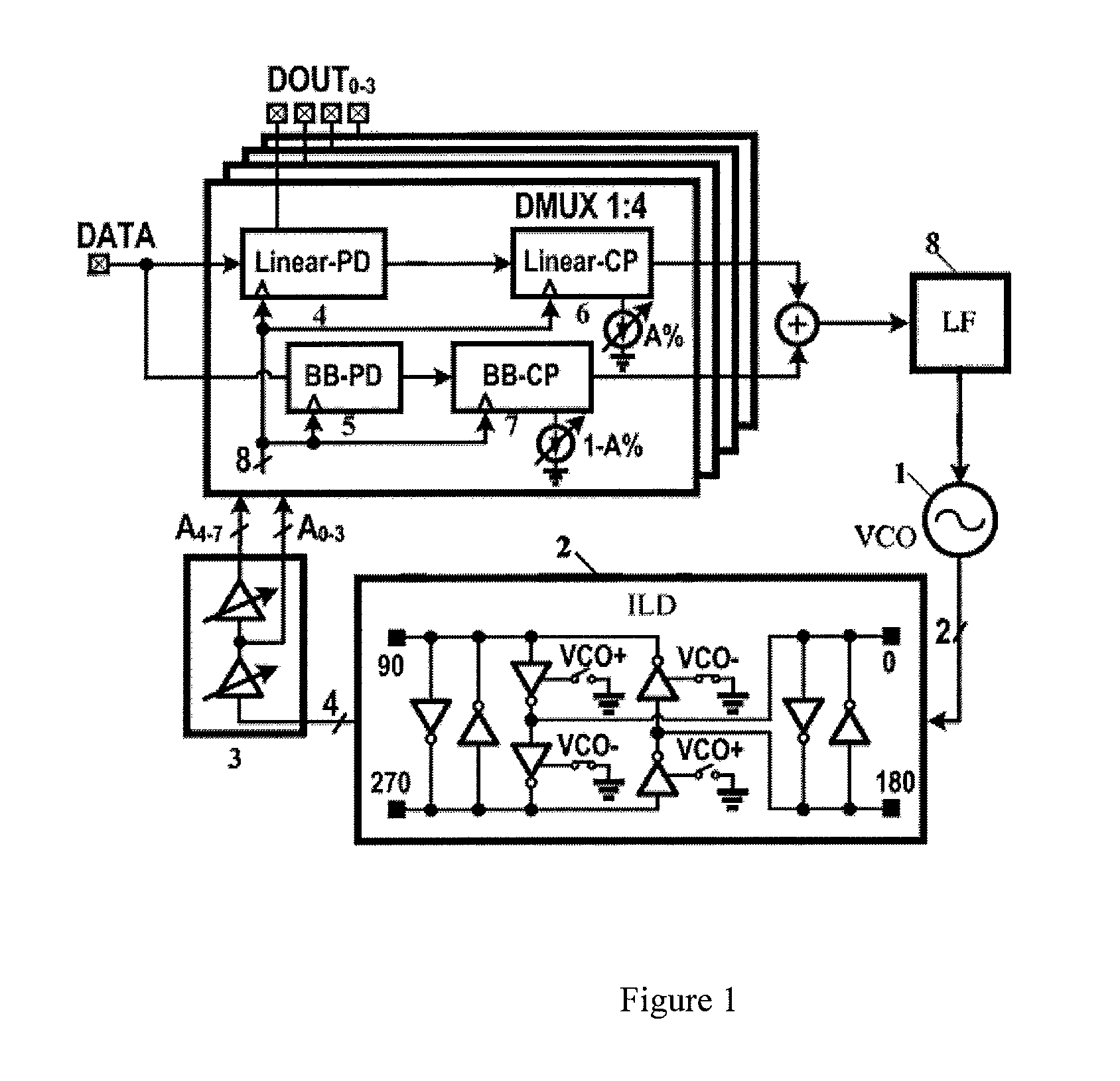
[0037]As shown in FIG. 1, the 25 Gbps clock and data recovery circuit (CDR) using ZCL (zero-crossing linearizing) is disclosed in this invention contains: Voltage-Controlled Oscillator 1 (VCO); Injection-Locked Divider 2 (ILD), which is connected to the output of VCO 1; variable delay unit 3, connected to the output of ILD 2; linearized phase detector (PD) 4 using ZCL technique, and bang-bang PD 5, connected the output of variable delay unit 3; linearized Charge Pump (CP) 6 and bang-bang CP 7, which connects to the output of linearized PD 4 and bang-bang PD 5 respectively; Loop Filter (LF) 8, which connects to the output of linearized CP 6 and bang-bang CP 7.

[0038]Wherein, linearized phase detector (PD) 4 and linearized Charge Pump (CP) 6, which connected to the output of linearized PD constituted linearize...


PUM


Abstract

A clock and data recovery (CDR) circuit employing zero-crossing linearizing (ZCL) technique. The circuit including a voltage controlled oscillator (VCO), an inject-locked divider (ILD), a variable delay unit, a linearized loop, a bang-bang loop, and a loop filter (LP). The differential clock generated by VCO passes through ILD for frequency dividing and variable delay unit to generate 8-phase clocks. Then using these clocks, the PDs over-sample the input data, followed by synchronization and logic operation to control the CPs output current pulses. These currents filtered by LP control the VCO to finish the loop. The circuit recovers 4 channel data and corresponding clocks of the input with low power broken-down and preferable jitter performance and locking property.

Description

FIELD OF INVENTION[0001]This patent is concerned with communication science and technology, and, particularly to a clock and data recovery circuit (CDR).BACKGROUND OF INVENTION[0002]Since the demand and the increasing of various portable devices, the data volume on the communication links is rising exponentially, requiring the wireline communication systems, especially the data center providing high-speed, accurate and stable data transmission solutions. Considering as the core of data center equipment and facilities, optical communication and high-speed wireline communication systems request drastic improvement in speed, power and stability, while in all its blocks, the clock and data recovery circuit determines the clock quality of the total receiver end and the jitter and bit error rate (BER) of the received data.[0003]Traditional CDRs usually adopt III-V processes likes GaAs, which is deemed as high-speed and low-noise material and perfect for radio frequency circuit. However, i...

Claims


Application Information

Patent Timeline
IPC IPC(8): H04L7/00
CPCH04L7/0087H04L7/0037H03L7/0807H03L7/081H03L7/085H03L7/087H04L7/033H03L7/00
Inventor WANG, ZHONGKAIBAI, RUICHIANG, PATRICK YIN
Owner FUDAN UNIV
Why Eureka
Try Eureka