Bicycle wheel securing structure

a technology for securing structures and bicycle wheels, which is applied in the direction of axle suspensions, release mechanisms, cycle equipments, etc., can solve the problems of difficult stopping of the risk of the lever member hitting an obstacle, and the inability to easily stop the rotation of the adjustment member, etc., to achieve the effect of convenient operation

Active Publication Date: 2015-03-12
SHIMANO INC
View PDF7 Cites 13 Cited by
  • Summary
  • Abstract
  • Description
  • Claims
  • Application Information

AI Technical Summary

Benefits of technology

[0027]The lever member can have a rotating shaft that is rotatably provided around an axis that intersects the axial direction, a lever main body that is provided integrally and rotatably with the rotating shaft and a cam structure that is movable relative to the head member in the axial direction in response to the rotation of the head member. In this case, if the lever main body is turned around the rotating shaft, the shaft member moves in the axial direction due to the cam structure and the securing and the fix releasing of the wheel securing structure to the frame can be easily carried out.
[0028]The rotation of the adjustment member can be easily stopped in a bicycle wheel securing structure that can adjust the final fixing position of the lever member.

Problems solved by technology

At this time, if the final position of the lever member is not along the frame (for example, the front form, the chain stay, or the seat stay) but is away from the frame, there is the risk that the lever member will hit an obstacle.
For this reason, a tool to turn the threaded member becomes necessary, so that the rotation of the adjustment member cannot be easily stopped.
Additionally, since a slit and a hole to pass through the threaded member are provided in the adjustment member, if foreign matter enters the slit or the hole, stopping the rotation of the adjustment member becomes more difficult.
Additionally, foreign matter will not easily enter the positioning mechanism.

Method used


Image

  • Bicycle wheel securing structure
  • Bicycle wheel securing structure
  • Bicycle wheel securing structure

Examples


first modified example

[0069]In the above-described embodiment, the movement regulation part 42 that regulates the movement range of the adjustment member 26 was configured by the O-ring 60 and the annular recess 62, but the present invention is not limited to this configuration. In the following explanations, regarding the parts that are different in shape, etc., from the above-described embodiment, the reference symbols of the above-described embodiment are indicated with three digits and the other parts are given the same reference symbols, with their explanations having been omitted.

[0070]As shown in FIG. 7, a movement regulation part 142 of the first modified example comprises a first movement regulation part 160 and a second movement regulation part 162. The first movement regulation part 160 regulates the movement of the adjustment member 126 in the first axial direction X1. The second movement regulation part 162 regulates the movement of the adjustment member 126 in the second axial direction X2....

second modified example

[0074]In the second modified example, the second movement regulation part has the same configuration as that in the first modified example, but the first movement regulation part is different from that in the first modified example. In the explanation for the second modified example, regarding the parts that are different in shape, etc., from the above-described embodiment and the first modified example, the reference symbols of the above-described embodiment and the first modified example are indicated with three digits and the other parts are given the same reference symbols, with their explanations having been omitted.

[0075]As shown in FIG. 8, the movement regulation part 242 of the second modified example comprises a first movement regulation part 260 and a second movement regulation part 162. The first movement regulation part 260 regulates the movement of the adjustment member 126 in the first axial direction X1. The second movement regulation part 162 regulates the movement o...

second embodiment

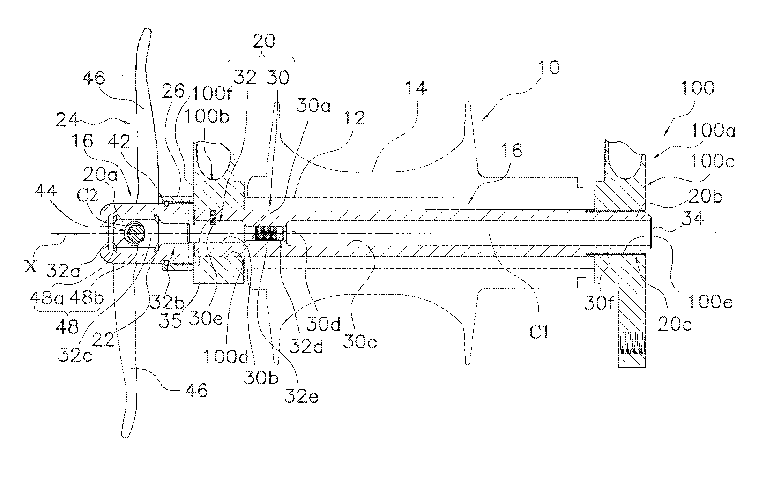
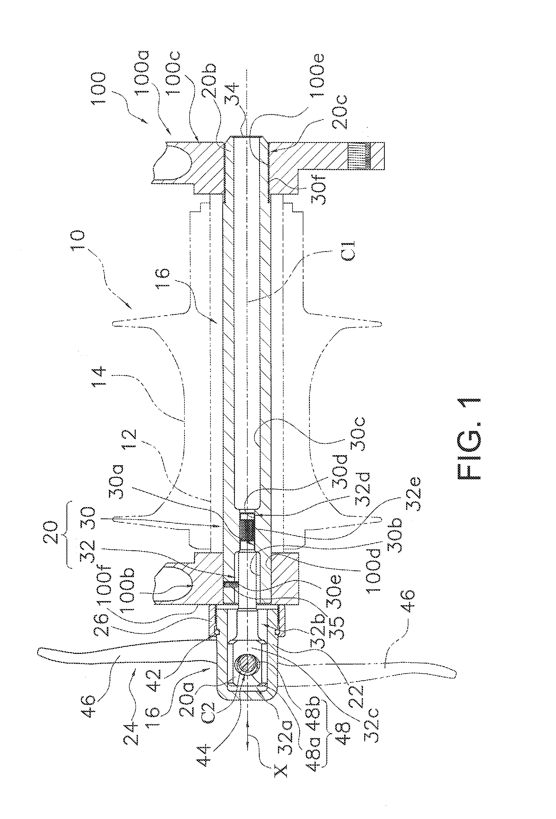
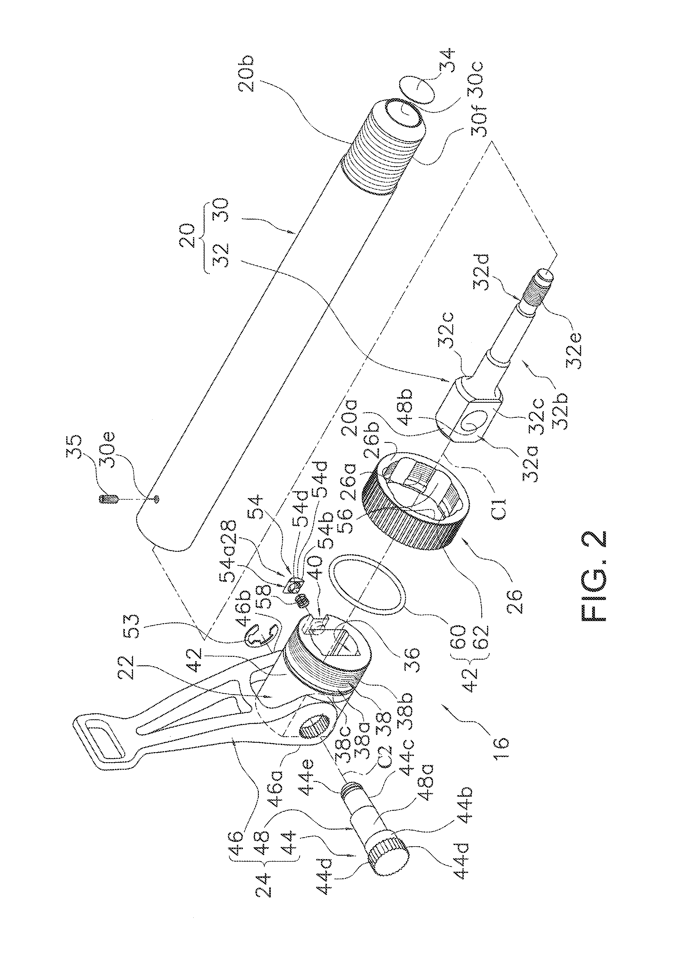
[0077]In FIG. 9, the bicycle wheel securing structure 316 according to the second embodiment of the present invention fixes a wheel of a bicycle to the frame 100 of the bicycle in the same way as in the first embodiment. Specifically, this structure fixes the hub 10 of the wheel of the bicycle to the frame 100. In the second embodiment, the bicycle hub 10 is a rear hub that can be mounted on the rear part of the frame 100. The hub 10 has the same configuration as that disclosed in the first embodiment, so the explanation has been omitted.

[0078]As shown in FIGS. 9, 10 and 11, the wheel securing structure 316 comprises a shaft member 20, a head member 322, a lever member 24, an adjustment member 326, a positioning member 328 (refer to FIG. 10) and a movement regulation part 42. The shaft member 20 comprises a first end portion 20a, a second end portion 20b and an engaging part 20c. The second end portion 20b is different from the first end portion 20a. The second engaging part 20c is ...


PUM


Abstract

A bicycle wheel securing structure is provided with a shaft member, a head member, a lever member, an adjustment member and a positioning mechanism.
The shaft member has a first end portion, a second end portion and an engaging part. The head member is movably disposed on the first end portion. The lever member is movably provided on the head member around a pivot axis that intersects with an axial direction of the shaft member to move the shaft member in the axial direction with respect to the head member. The adjustment member is movably provided on the head member in the axial direction and that can adjust a final fixing position of the lever member. The positioning mechanism is provided between the head member and the adjustment member to selectively maintain a position of the adjustment member in a plurality of axially spaced apart locations.

Description

CROSS-REFERENCE TO RELATED APPLICATIONS[0001]This application claims priority to Japanese Patent Application No. 2013-186108, filed on Sep. 9, 2013, and Japanese Patent Application No. 2014-092902, filed on Apr. 28, 2014. The entire disclosures of Japanese Patent Application Nos. 2013-186108 and 2014-092902 are hereby incorporated herein by reference.BACKGROUND[0002]1. Field of the Invention[0003]This invention generally relates to a bicycle wheel securing structure. More specifically, the present invention relates to a bicycle wheel securing structure for detachably securing a wheel to the frame of a bicycle.[0004]2. Background Information[0005]A bicycle wheel securing structure for detachably securing a wheel to the frame of a bicycle is conventionally known (for example, U.S. Pat. No. 7,537,291). A conventional bicycle wheel securing structure comprises a shaft member, a head member, a lever member and an adjustment member. The shaft member comprises a threaded portion that can b...

Claims


Application Information

Patent Timeline
Patent Type & Authority Applications(United States)
IPC IPC(8): B62K25/02
CPCB62K2206/00B62K25/02
Inventor NAKAJIMA, JUNKOSHIYAMA, KAZUKI
Owner SHIMANO INC
Why Eureka
Try Eureka