
Lens coating/contamination electronic detection

a technology of electronic detection and lens coating, applied in the field of optical systems, can solve the problems of distorted light collected by these lenses/objectives, affecting measurement and/or inspection results,

Inactive Publication Date: 2015-03-12
GLOBALFOUNDRIES INC
View PDF1 Cites 7 Cited by
  • Summary
  • Abstract
  • Description
  • Claims
  • Application Information

AI Technical Summary

Benefits of technology

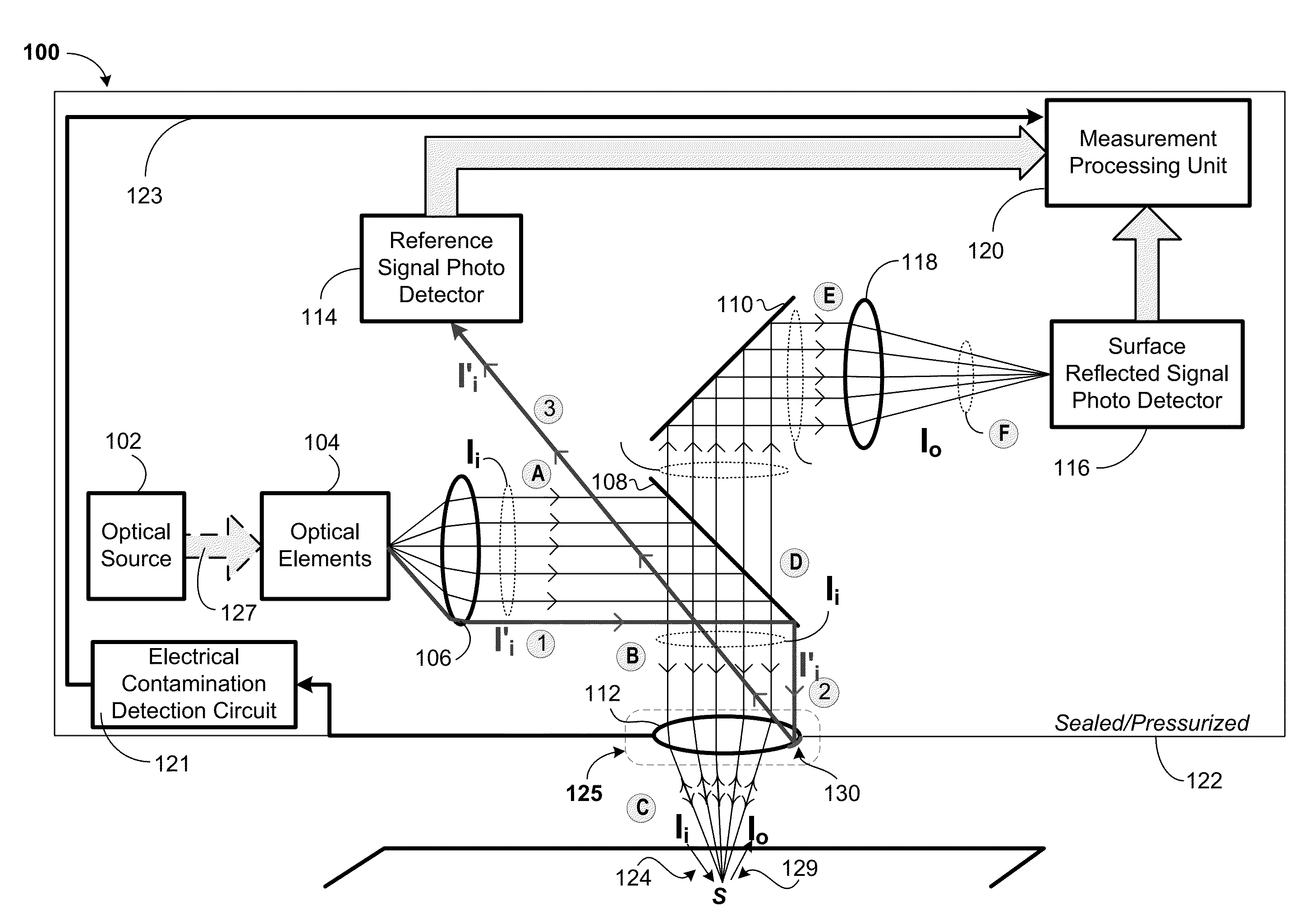
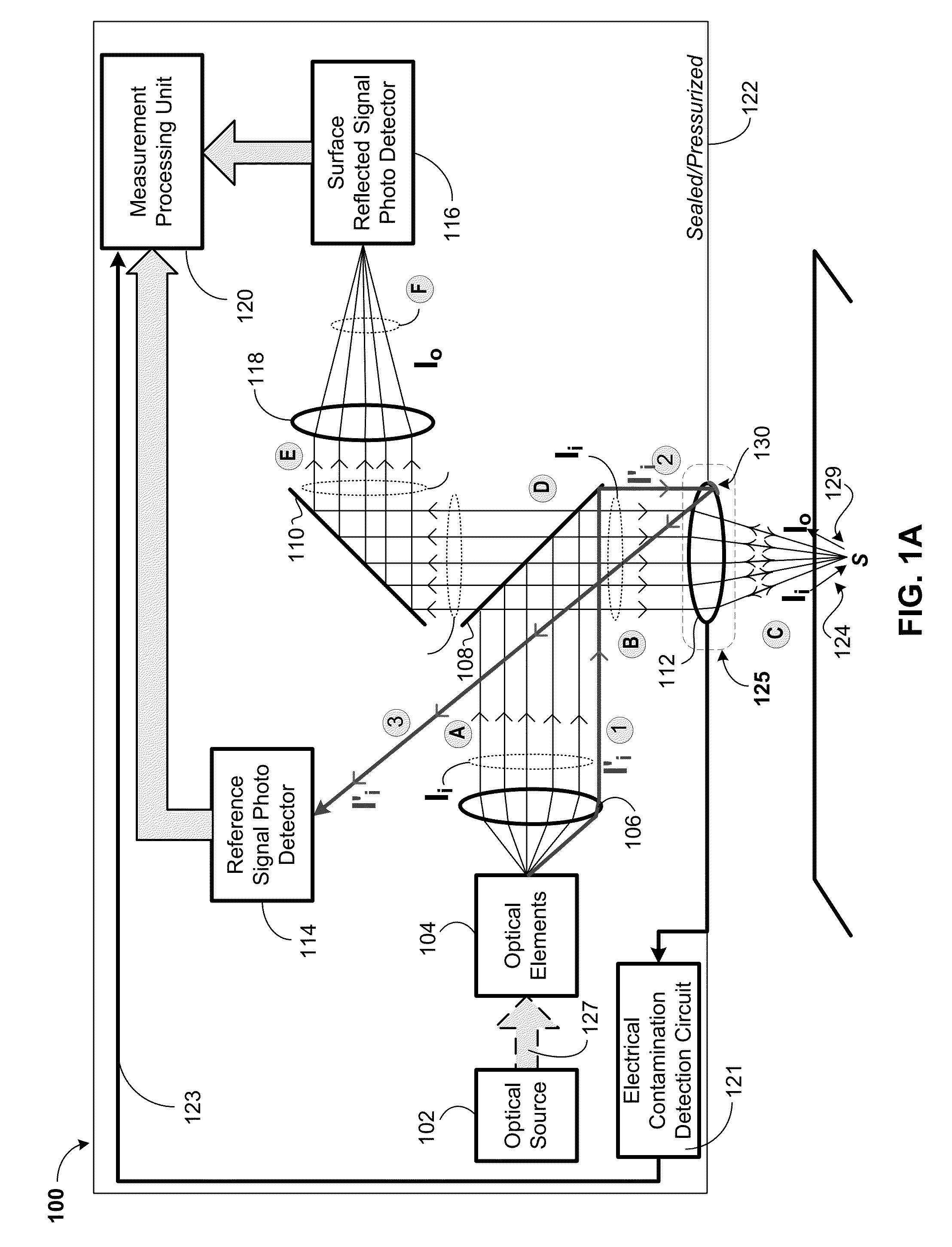
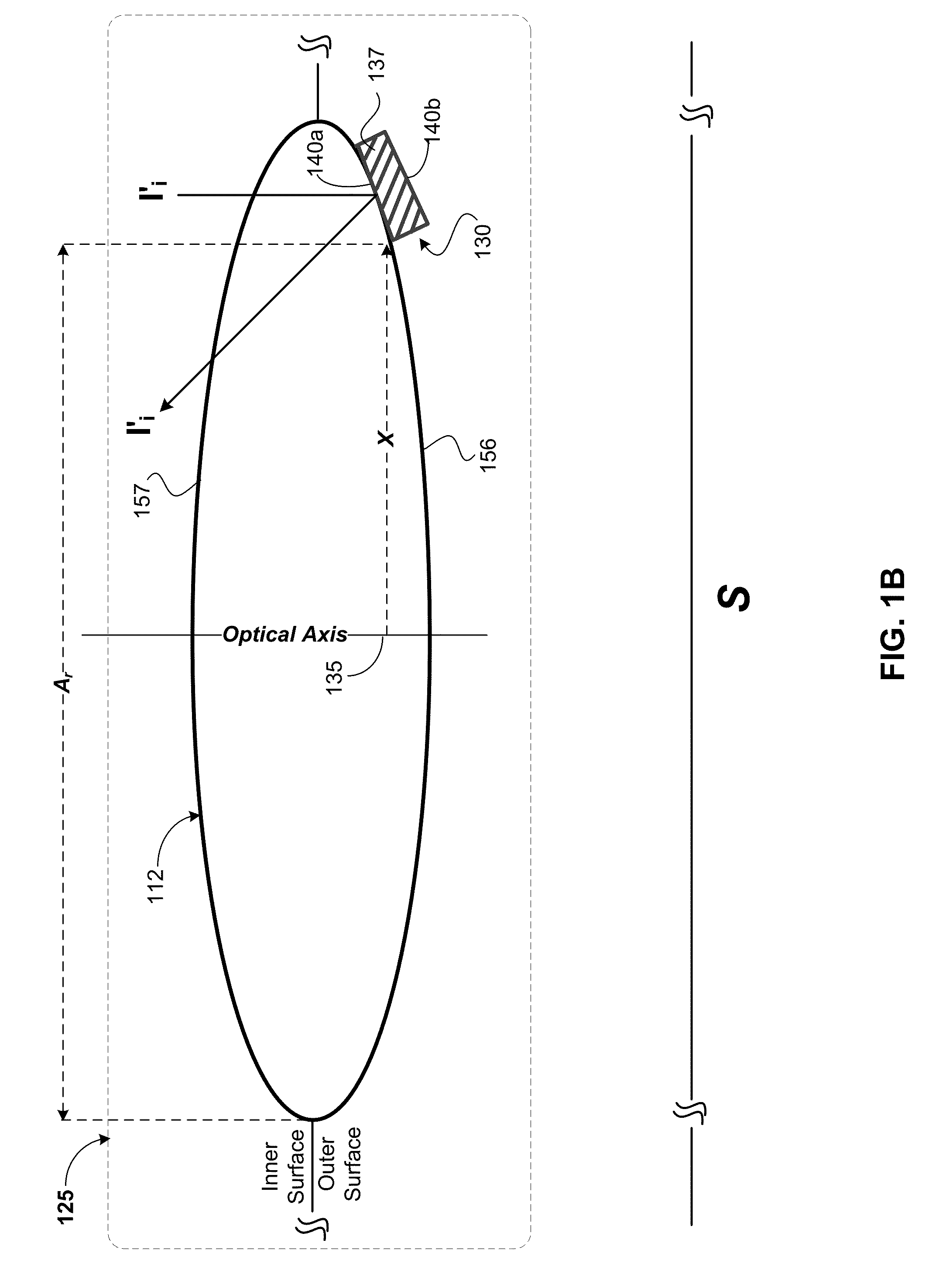
The patent describes a way to detect contaminants that can affect optical measurements. It involves using an optical element with a capacitor plate on its surface, and measuring the changes in capacitance caused by the contaminants. This can be done using a simple alternating signal, and the detected contaminants can be identified based on their resistance value. The technical effect of this invention is to improve the accuracy of measurements and detect contaminants on optical equipment, ensuring the integrity of the overall optical system.

Problems solved by technology

In manufacturing environments these surfaces may often release gases or vapors that can coat the lens / objectives in such a manner that light collected by these lens / objectives is distorted and / or attenuated.
The measurement and / or inspection results may thus be distorted as a result of the measurement being influenced by the existing contamination.

Method used


Image

  • Lens coating/contamination electronic detection
  • Lens coating/contamination electronic detection
  • Lens coating/contamination electronic detection

Examples


Embodiment Construction

[0017]As will be appreciated by one skilled in the art, aspects of the present invention may be embodied as a system, method or computer program product. Accordingly, aspects of the present invention may take the form of an entirely hardware embodiment, an entirely software embodiment (including firmware, resident software, micro-code, etc.) or an embodiment combining software and hardware aspects that may all generally be referred to herein as a “circuit,”“module” or “system.” Furthermore, aspects of the present invention may take the form of a computer program product embodied in one or more computer readable medium(s) having computer readable program code embodied thereon.

[0018]Any combination of one or more computer readable medium(s) may be utilized. The computer readable medium may be a computer readable signal medium or a computer readable storage medium. A computer readable storage medium may be, for example, but not limited to, an electronic, magnetic, optical, electromagne...


PUM


Abstract

A contamination detection apparatus may include an optical element having an outer surface and an other surface opposing the outer surface, a first capacitor plate located on the outer surface at an outer periphery of the optical element, and a second capacitor plate located on the outer surface at the outer periphery of the optical element. The second capacitor plate is located adjacent the first capacitor plate and separated from the first capacitor by a gap to form a capacitor, whereby a contaminant is electrically detected based on the contaminant entering the gap and varying a capacitance value corresponding to the capacitor.

Description

BACKGROUND[0001]a. Field of the Invention[0002]The present invention generally relates to optical systems, and more particularly to detecting contamination within such optical systems.[0003]b. Background of Invention[0004]Optical metrology and inspection equipment such as, for example, reflectometers may often use high power optical lens / objectives in close proximity to surfaces for measurement and / or inspection purposes. In manufacturing environments these surfaces may often release gases or vapors that can coat the lens / objectives in such a manner that light collected by these lens / objectives is distorted and / or attenuated. The measurement and / or inspection results may thus be distorted as a result of the measurement being influenced by the existing contamination.BRIEF SUMMARY[0005]According to one or more embodiments, it may therefore, be advantageous, among other things, to electronically detect contaminants (e.g., gases / vapors) that may coat the optical components (e.g., lenses...

Claims


Application Information

Patent Timeline
IPC IPC(8): G01N27/24G01N27/22
CPCG01N27/228G01N27/24G01N21/55G01N27/20G01N27/22G01N2021/155
Inventor STROCCHIA-RIVERA, CARLOS
Owner GLOBALFOUNDRIES INC
Learn More