
Dynamic shoulder orthosis with rehabilitating adduction

a shoulder and dynamic technology, applied in the field of shoulder orthosis, can solve the problems of inability to operate unaided by the patient alone, limited exercise, and difficulty in adjusting mechanisms, and achieve the effect of minimizing contraction and stress of the injured muscles

Active Publication Date: 2015-03-12
UNIV DE MONTREAL +2
View PDF4 Cites 6 Cited by
  • Summary
  • Abstract
  • Description
  • Claims
  • Application Information

AI Technical Summary

Benefits of technology

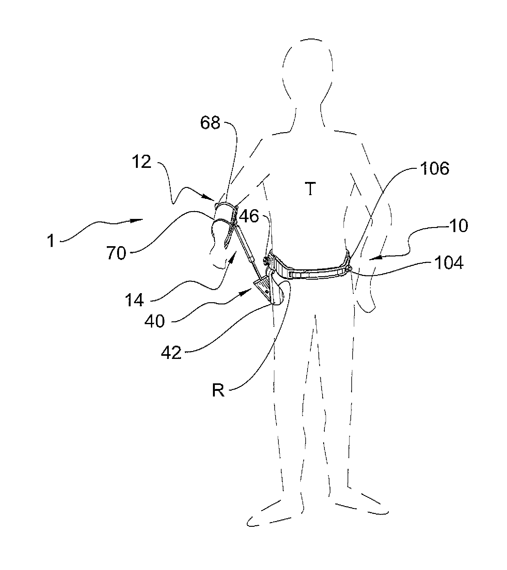
The present invention is a shoulder orthosis for surgically repaired rotator cuffs that allows the patient to exercise their arm muscles while reducing stress on the injury. It allows for adduction and flexion / extension of the forearm, keeping the arm in a constant position relative to the body. The orthosis also stabilizes the arm at different angles and prevents frozen shoulder and stiffness in the joints. It is comfortable and functional for daily activities. The invention includes a waist belt, arm splint, extendible connector member, damper means, locking means, and splint swing motion compensating means. It provides long-term support of the arm while minimizing contraction of the injured muscles.

Problems solved by technology

This exercising is limited to a certain set of movements that minimize the use of the injured or repaired muscles.
But these height adjustment mechanisms often require external intervention and cannot be operated unaided by the patient alone.
Some also require complex or lengthy procedures, requiring the orthosis to be firstly removed, or involving spare parts and even special tools.
Some also comprise unstable harnesses and splint, or they comprise multiple support structures which are often cumbersome and uncomfortable.
Furthermore, most of these orthosis do not enable any kind of free arm movement by the patient's arm, which is a major inconvenience when several weeks of rehabilitation are required.
Furthermore orthosis known in the art do not allow for the concurrent flexion / extension of the forearm around the injured arm elbow.

Method used


Image

  • Dynamic shoulder orthosis with rehabilitating adduction
  • Dynamic shoulder orthosis with rehabilitating adduction
  • Dynamic shoulder orthosis with rehabilitating adduction

Examples


Embodiment Construction

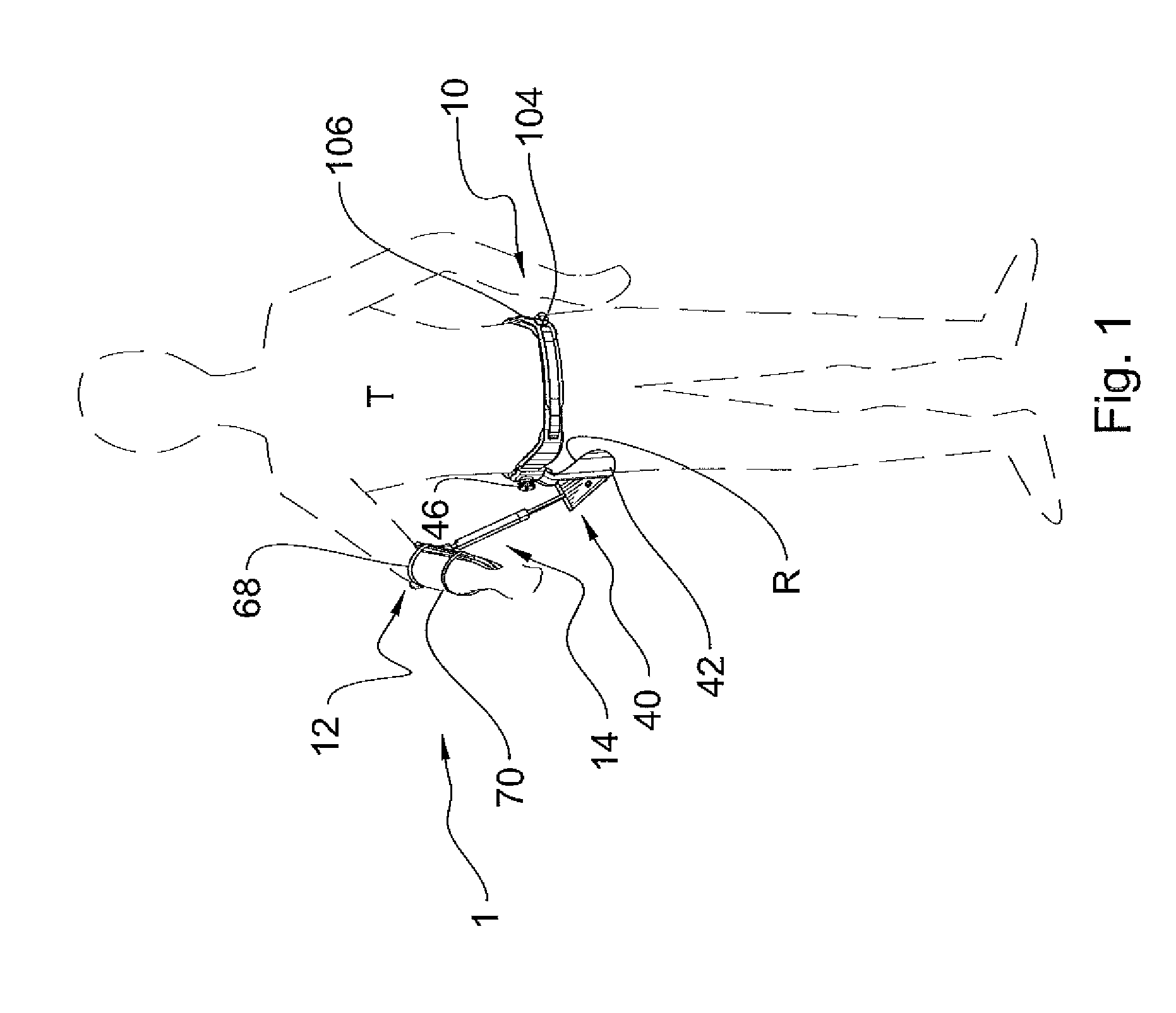
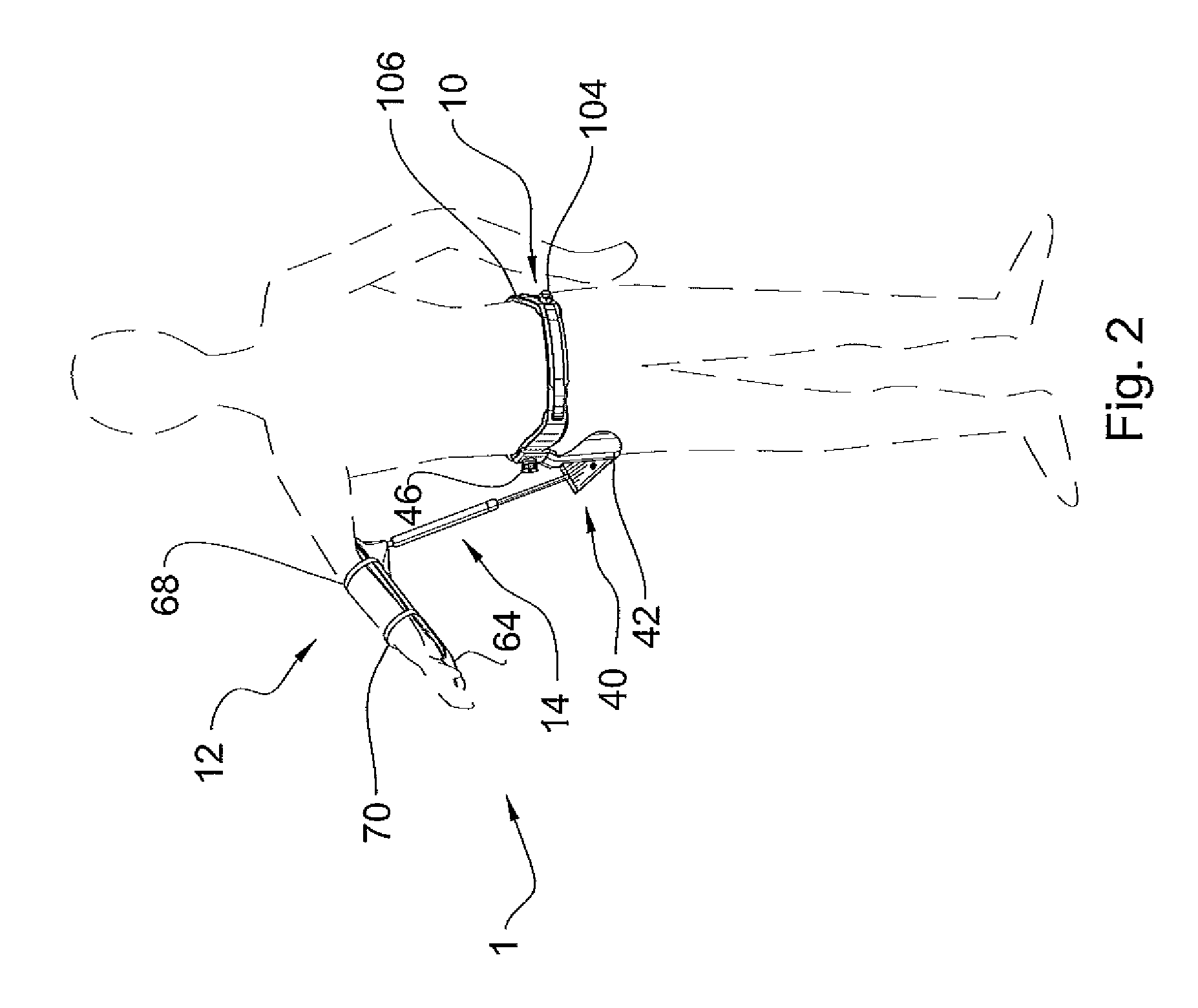
[0039]Referring to accompanying FIGS. 1-14, there is shown a shoulder orthosis 1 according to a preferred embodiment of the present invention. Shoulder orthosis 1 comprises a waist harness 10, a forearm splint 12, and an extendible connector member 14 interconnecting harness 10 and splint 12.

[0040]Referring more specifically to FIGS. 3-5 and 10, waist harness 10 comprises a waist belt 16 having the general aspect of a strip made out of a fairly stiff yet extensible, semi-flexible and resilient material. Waist belt 16 is sized and shaped as to conformingly fit about the patient's waist adjustably to various waist lines. Waist belt 16 defines a baseline 20, a back section 22, first and second frontal sections 24, 26 each of which opposite back section 22, first and second hip sections 28, 30 opposite each other, an interior face 29 being the lateral section of waist belt 10 in contact with the patient, and an exterior face 31 opposite inner face 29. Hook and loop fastener band members...


PUM


Abstract

A shoulder orthosis for long term support of a patient's arm in postoperative shoulder immobilization posture for rotator cuff tears, comprising a waist belt, an arm splint, and a piston and cylinder assembly interconnecting the waist belt to the splint and biasing the splint to an abduction upper limit position. The orthosis provides stable support of the forearm about a horizontal plane, while enabling both pivotal movement of the arm about a vertical axis intersecting the patient's elbow and towards or away from the patient's torso within this horizontal plane. This orthosis also enables cyclical up and down motion of the splint, the downward motion being healthy adductor-assisted against the bias of the piston and cylinder assembly. A lock system releasably locks the piston and cylinder at a selected retracted position of the piston rod.

Description

FIELD OF THE INVENTION[0001]The present invention relates to shoulder orthosis for supporting the arm in abduction after a surgical repair of tear injuries to the rotator cuff, and more specifically to shoulder orthosis with adjustable arm stabilisation height enabling cyclical exercising of the uninjured arm adductor muscles.BACKGROUND OF THE INVENTION[0002]Muscle tears are degenerative type bodily injuries, whose occurrence increase with old age, in particular beyond 70 to 80 years of age. Shoulder muscle tear injuries occur typically when a person repetitively lifts heavy loads above his / her head, and will appear regularly in activities such as swimming, window cleaning, freight handling, strength conditioning exercising, and the like.[0003]It often happens that an important part of the medical treatment of a repaired shoulder muscle requires the stabilization and support of the arm in abduction (away from the patient's sagittal plane) during the rehabilitation healing period whi...

Claims


Application Information

Patent Timeline
IPC IPC(8): A61F5/01
CPCA61F5/013A61F5/3753
Inventor BEGON, MICKAELBLEAU, JACINTENOBERT, SERGETETREAULT, PATRICE
Owner UNIV DE MONTREAL
Learn More