Battery pole, electronic cigarette using the battery pole, and method for identifying an atomizer of the electronic cigarette
- Summary
- Abstract
- Description
- Claims
- Application Information
AI Technical Summary
Benefits of technology
Problems solved by technology
Method used
Image
Examples
first embodiment
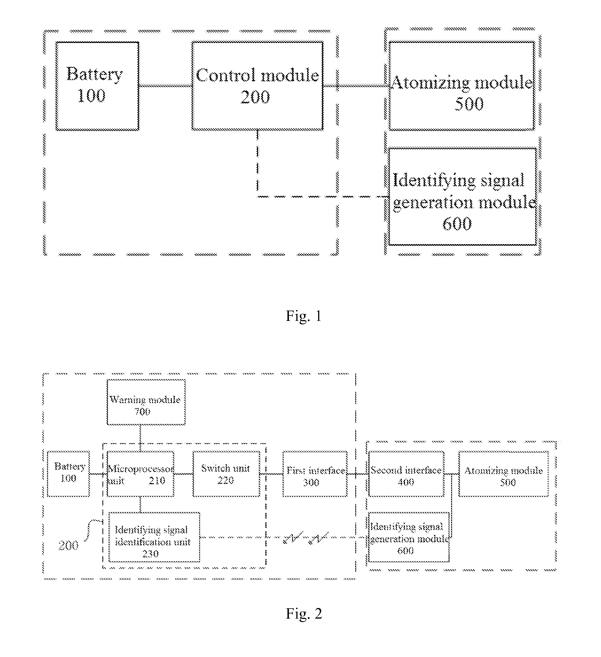
[0073]FIG. 2 is a block diagram of an electronic cigarette of the present application; and FIG. 3 is a circuit diagram of the electronic cigarette shown in FIG. 2.
[0074]In the first embodiment, the identification signal generation module 600 needs to receive a detecting signal from the control module 200 at first, and then is enabled to send out the identification signal; and the identification signal is sent to the control module 200 by wireless transmission.
[0075]Particularly, the battery pole includes a battery 100, a control module 200, a first interface 300, and a warning module 700; and the atomizer includes a second interface 400, an atomizing module 500, and an identification signal generation module 600.
[0076]The control module 200 is connected to the battery 100, the first interface 300, and the warning module 700 respectively; and the second interface 400 is connected to the first interface 300, the atomizing module 500 and the identification signal generation module 600 ...
second embodiment
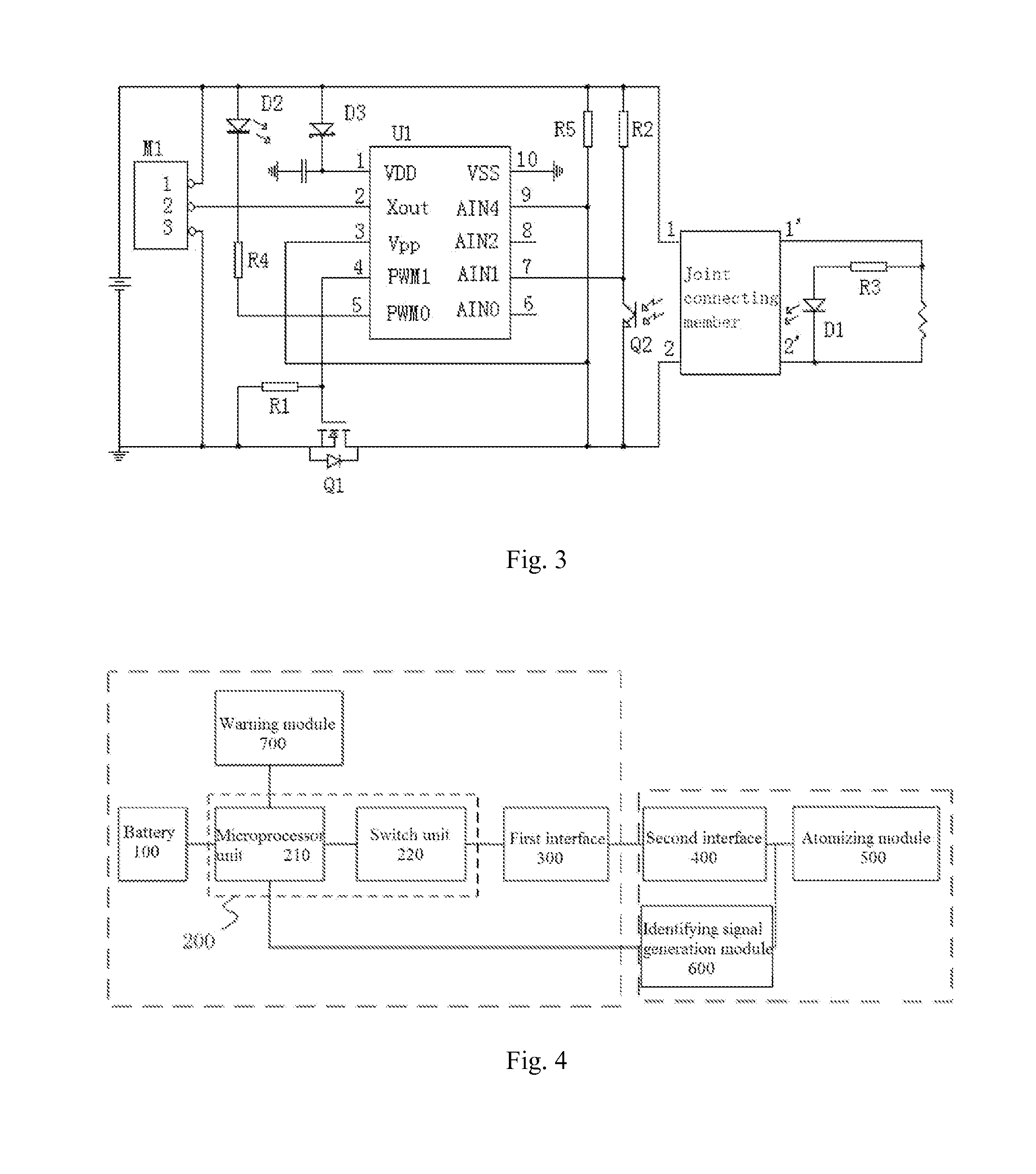
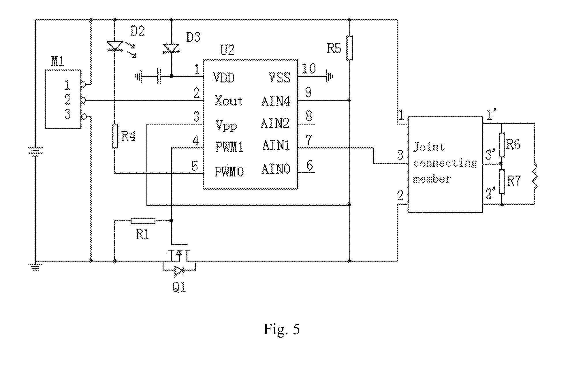
[0092]FIG. 4 is a block diagram of an electronic cigarette of the present application; and FIG. 5 is a circuit diagram of the electronic cigarette shown in FIG. 4.
[0093]In the second embodiment, only after the identification signal generation module 600 receives a detecting signal from the control module 200, the identification signal generation module 600 sends out an identification signal. The identification signal is sent to the control module 200 by wired transmission.
[0094]The control module 200 includes a microprocessor unit 210 and a switch unit 220.
[0095]The microprocessor unit 210 is connected to the battery 100, the switch unit 220, and the identification signal generation module 600 respectively; and the switch unit 220 is further connected to the first interface 300.
[0096]The microprocessor unit 210 is configured for receiving and identifying the identification signal generated by the identification signal generation module 600 by the wired transmission. The microprocess...
third embodiment
[0120]FIG. 9 is a flow chart of a method for identifying an atomizer, in accordance with the present application.
[0121]The difference between the method of the third embodiment and the method of the second embodiment is that: in the method of the second embodiment the atomizer is identified after every smoking action applied to the electronic cigarette; while in the method of the third embodiment, the atomizer is identified when the number of the smoking actions applied to the electronic cigarette reaches a preset value. Besides, in the method of the third embodiment, the atomizer is not identified again after one identification action for the atomizer is completed.
[0122]Particularly, compared with the method of the first embodiment, the method of the third embodiment further comprises:
[0123]Step 10: between the step 0 and the step 01, using the control module 200 to detect a smoking trigger signal generated by a smoking trigger unit.
[0124]Step 20: between the step 10 and the step 0...
PUM
 Abstract
Description
Claims
Application Information
 - R&D
- Intellectual Property
- Life Sciences
- Materials
- Tech Scout
- Unparalleled Data Quality
- Higher Quality Content
- 60% Fewer Hallucinations
Browse by: Latest US Patents, China's latest patents, Technical Efficacy Thesaurus, Application Domain, Technology Topic, Popular Technical Reports.
© 2025 PatSnap. All rights reserved.Legal|Privacy policy|Modern Slavery Act Transparency Statement|Sitemap|About US| Contact US: help@patsnap.com


