Turn signal indicator device

a technology of turning signal and indicator device, which is applied in the direction of contact operating parts, contact mechanisms, transportation and packaging, etc., can solve the problems of difficult to make it compact, affecting the operation of drivers, and liable to be complicated, so as to reduce the number of electric contacts, prevent the effect of operation mistake, and simplify the structure of the operation lever

Active Publication Date: 2015-03-19
YAZAKI CORP
View PDF18 Cites 11 Cited by
  • Summary
  • Abstract
  • Description
  • Claims
  • Application Information

AI Technical Summary

Benefits of technology

[0039]According to the turn signal indicator device having the structure described in (8) above, a driver can easily recognize a current state in accordance with the type of output notification sound with the first turn signal indication and the second turn signal indication distinguished from each other. Accordingly, an operation mistake can be prevented.
[0040]According to the present invention, the structure of an operation lever can be simplified and the number of electric contacts can be reduced. Besides, an area (region) where the electric contacts are provided can be made small.

Problems solved by technology

Since the turn signal indicating operation lever has the aforementioned structure, the mechanism is liable to be complicated, and it is difficult to make it compact.
Therefore, some drivers may feel it difficult to operate because of sensuous differences among individuals.

Method used


Image

  • Turn signal indicator device
  • Turn signal indicator device
  • Turn signal indicator device

Examples


first embodiment

Structure of Device

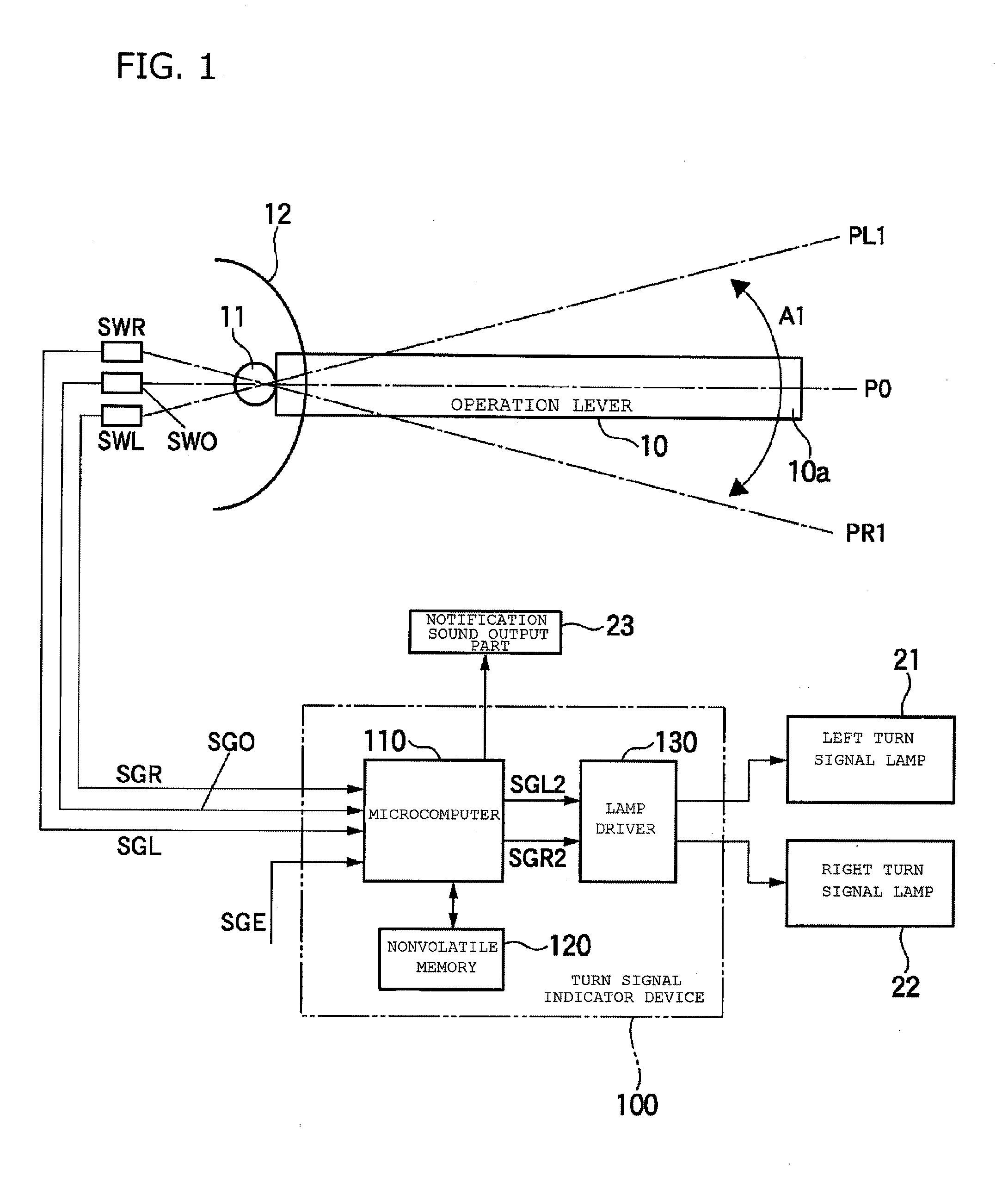
[0051]An example of the structure of a turn signal indicator device 100 according to the present invention is illustrated in FIG. 1.

Explanation of Operation Lever

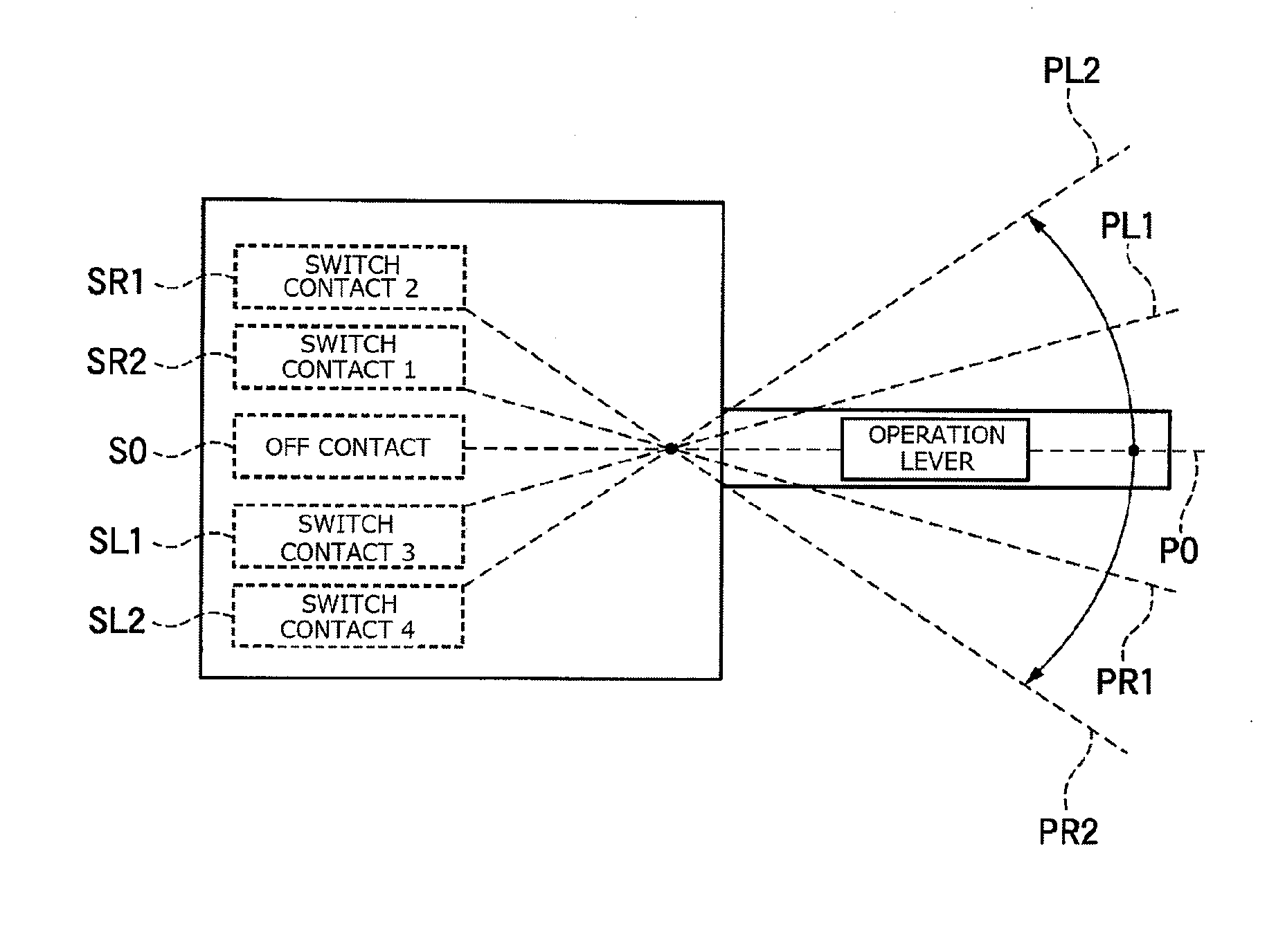
[0052]An operation lever 10 of FIG. 1 is operated by a driver for operating a turn signal indicator of a vehicle. This operation lever 10 is set on a steering column 12 so as to be swingable around a rotating shaft 11 in a direction of an arrow A1. Besides, when no external force is applied, the operation lever 10 is positioned in a neutral position P0 as illustrated in FIG. 1, and at this time, it protrudes rightward from the steering column 12 to be retained in a substantially horizontal state. When the driver moves a lever end 10a upward or downward, it can be moved to an operation position PL1 or PR1.

[0053]Besides, even when the operation lever 10 is moved to the operation position PL1 or PR1, if the driver releases a force applied for operating the operation lever 10, the operation lever 10 automatic...

second embodiment

Structure of Device

[0086]An example of a turn signal indicator device 100 of the present embodiment is illustrated in FIG. 3. In the structure illustrated in FIG. 3, pressure sensors 31 and 32 are additionally provided. Apart from them, the structure is the same as that illustrated in FIG. 1. Incidentally, like reference numerals are used in FIG. 3 to refer to elements corresponding to those illustrated in FIG. 1.

[0087]As illustrated in FIG. 3, the pressure sensors 31 and 32 for detecting a pressing force applied to the operation lever 10 are provided in prescribed portions of the steering column 12. The upper pressure sensor 31 detects a pressing force applied by a driver to the operation lever 10 when the operation lever 10 is moved to the operation position PL1. The lower pressure sensor 32 detects a pressing force applied by the driver to the operation lever 10 when the operation lever 10 is moved to the operation position PR1.

[0088]An electric signal PrL corresponding to a pres...

third embodiment

Structure and Operation of Device

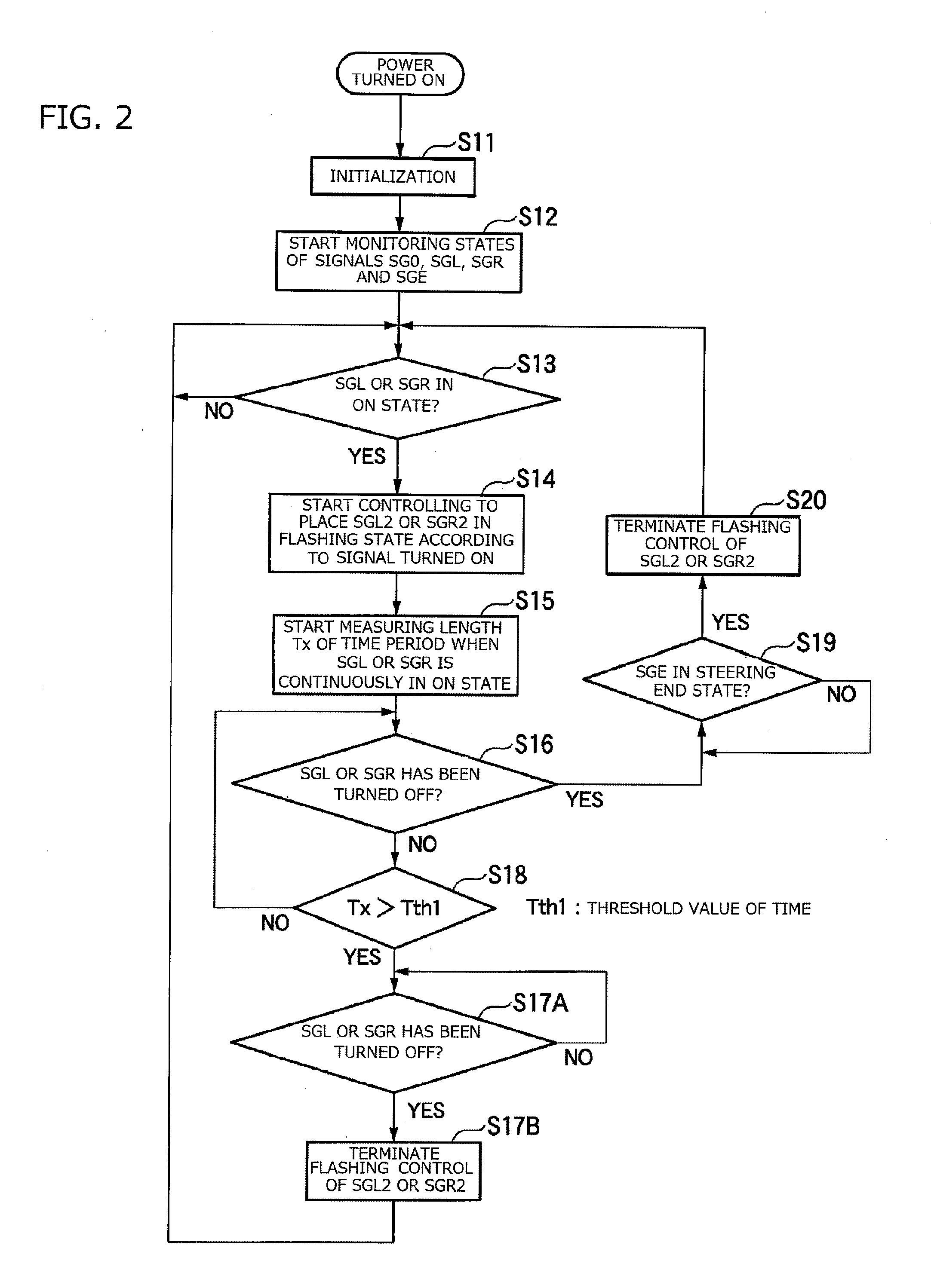
[0105]The structure of a turn signal indicator device 100 of the present embodiment is the same as that illustrated in FIG. 1. Besides, the operation of the turn signal indicator device 100 of the present embodiment is illustrated in FIG. 5. Incidentally, the operation of FIG. 5 is a modification of the operation of FIG. 2, and like step numbers are used to refer to like processing.

[0106]The operation of FIG. 5 will now be described. The operation performed in steps S11 to S19 of FIG. 5 is the same as that illustrated in FIG. 2.

[0107]In step S20B of FIG. 5, the microcomputer 110 regards that a termination operation of the turn signal indication has been detected, and controls the left turn signal control signal SGL2 and the right turn signal control signal SGR2 to be turned off. Thus, the flashing of the left turn signal lamp 21 or the right turn signal lamp 22 is terminated to switch the lamp to an extinction state. Incidentally, in this case, the o...


PUM


Abstract

There is provided a turn signal indicator device that drives a turn signal indicators provided on a vehicle based on on/off states of a switch, and includes an operation state discrimination part that discriminates between first turn signal indication for lane change of the vehicle and second turn signal indication for course change of the vehicle based on on/off signals supplied from the switch.

Description

CROSS REFERENCE TO RELATED APPLICATIONS[0001]This application is a continuation of PCT application No. PCT / JP2013 / 071284, which was filed on Aug. 6, 2013 based on Japanese Patent Application (No. 2012-175223) filed on Aug. 7, 2012, the contents of which are incorporated herein by reference.BACKGROUND OF THE INVENTION[0002]1. Technical Field[0003]The present invention relates to a turn signal indicator device for a vehicle.[0004]2. Background Art[0005]For example, in the case where a vehicle changes its course by turning right or left at a road intersection (hereinafter, which vehicle's operation to change its course by turning right or left will be designated as course change), a driver should indicate a turn signal (display) so that drivers of the other vehicles can recognize the turn signal. Also in the case where, for example, a vehicle changes its traveling lane in a road having a plurality of lanes running in parallel (hereinafter, which vehicle's operation to change a travelin...

Claims


Application Information

Patent Timeline
Patent Type & Authority Applications(United States)
IPC IPC(8): H01H21/24B60Q1/42
CPCB60Q1/42H01H21/24B60Q1/343B60Q1/40B60Q1/346B60Q1/1461B60Q1/34B60Q1/1484B60Q1/1469
Inventor MIZUNO, YOSHIYUKIAKAHORI, HIDEHIRO
Owner YAZAKI CORP
Why Eureka
Try Eureka