Coned disc spring

a disc spring and disc spring technology, applied in the direction of ring springs, belleville-type springs, wound springs, etc., can solve the problems of increasing the number of parts and production costs, and limited design, and achieve non-linear load characteristics, non-linear load characteristics, and the application range of the stroke can be set to be large.

Active Publication Date: 2015-03-19
NHK SPRING CO LTD
View PDF4 Cites 4 Cited by
  • Summary
  • Abstract
  • Description
  • Claims
  • Application Information

AI Technical Summary

Benefits of technology

[0007]An object of the present invention is to provide an elliptical coned disc spring that can be accommodated in a rectangular installation space, which can yield non-linear load characteristics, and which can reduce stress differences between a bending part at a long radial part side and a bending part at a short radial part side.
[0009]In the coned disc spring of the present invention, since the body has a disc shape, the same non-linear load characteristics can be obtained as those of conventional coned disc springs in which an outer circumference has a round shape. Furthermore, the outer circumference of the body has an elliptical shape, and the long diameter and the short diameter can be properly set, and therefore, the elliptical coned disc spring of the present invention can be accommodated in a rectangular installation space. In an elliptical coned disc spring in which the body has an elliptical shape, when the plate width of the long radial part and the plate width of the short radial part are set to be equal, generated stress of the bending part at the long radial part side is greater than that of the bending part at the short radial part side having a large radius of curvature. However, in the elliptical coned disc spring t of the present invention, since the plate width of the long radial part is set to be greater than the plate width of the short radial part, the stress difference between the bending part at a long radial part side and the bending part at a short radial part side can be reduced. As a result, the generated stress can be equalized in a circumferential direction of the body. Therefore, the elliptical coned disc spring of the present invention is different from conventional elliptical coned disc springs, and an application range (load) of a stroke can be set to be large without depending on stress of the bending part at the long radial part side having a small radius of curvature.
[0010]In the coned disc spring of the present invention, various structures can be applied. For example, an aspect in which an inner diameter of a long axial part is set to be not less than an inner diameter of a short axial part can be used. In this aspect, the stress difference between the bending part at a long radial part side and the bending part at a short radial part side can be effectively reduced, and as a result, the generated stress can be effectively equalized in a circumferential direction of the body.
[0011]According to the elliptical coned disc spring of the present invention, effects that can be accommodated in a rectangular installation space, which can yield non-linear load characteristics, which can reduce stress differences between a bending part at a long radial part side and a bending part at a short radial part side, and the like, are obtained.

Problems solved by technology

Therefore, the number of parts and production cost are increased.
As a result, the design is limited.

Method used


Image

  • Coned disc spring
  • Coned disc spring
  • Coned disc spring

Examples


Embodiment Construction

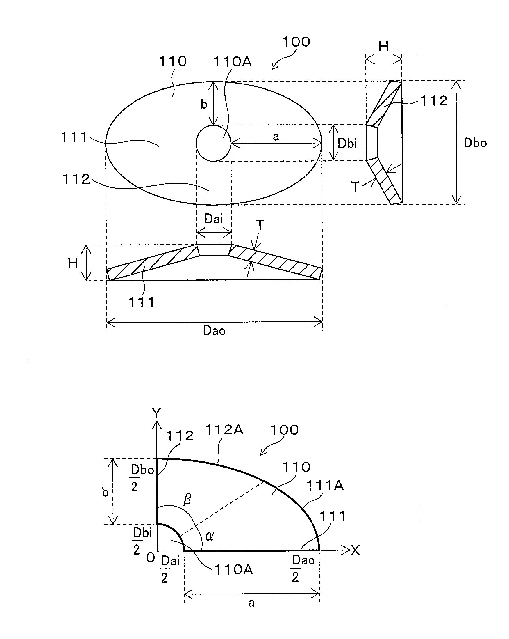
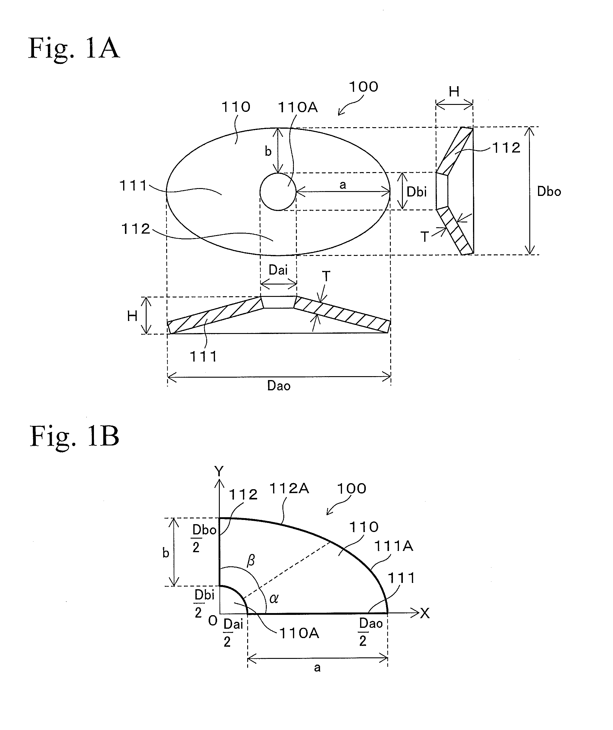
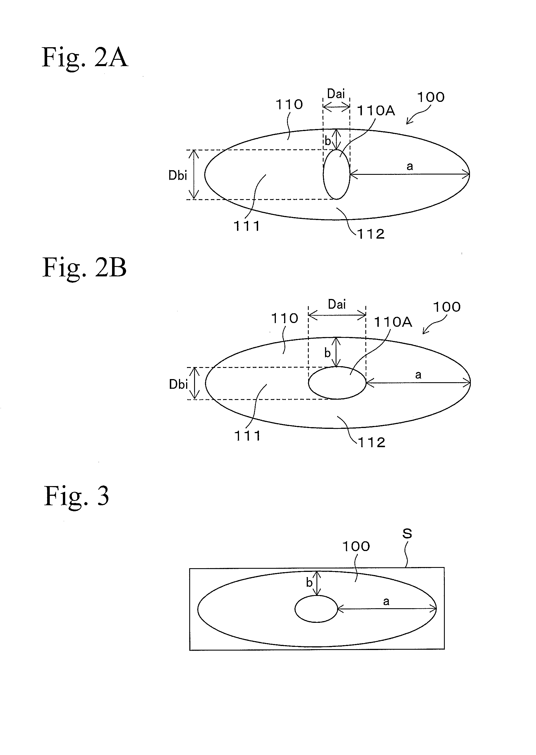
[0021]In the following, an embodiment of the present invention will be explained with reference to the figures. FIGS. 1A to 2B are drawings showing structures of an elliptical coned disc spring according to an embodiment of the present invention. Here, in FIG. 1B, an XY coordinate system is set, the center of an ellipse is set to the origin in the XY coordinate system, a part having a long diameter of the ellipse (long axial part) is set to an X axis direction, and a part having a short diameter of the ellipse (short axial part) is set to a Y axis direction. In FIG. 1B, only quadrant one of the XY coordinate system is shown as a matter of convenience, since the ellipse coned disc spring 100 has a symmetrical shape against each of the X axis and the Y axis.

[0022]The elliptical coned disc spring 100 is used in various applications such as a pressure means, a shock absorbing means, etc. The elliptical coned disc spring 100 (coned disc spring) has a disc shape (approximately conical), f...


PUM


Abstract

An elliptical coned disc spring can be accommodated in a rectangular installation space, can yield non-linear load characteristics, and can reduce stress differences between a bending part at a long radial part side and a bending part at a short radial part side. An elliptical coned disc spring has a body in which an outer circumference is an ellipse in a disc shape. A hole is formed at the center of the body. The hole may have various shapes such as a circle, an ellipse, etc. The body has a long radial part 111 and a short radial part. A plate width of the long radial part is set to be greater than a plate width of the short radial part (that is, a>b).

Description

TECHNICAL FIELD[0001]The present invention relates to a coned disc spring that can be used in various applications, such as, as a pressing means, a shock absorbing means, etc. Specifically, the present invention relates to a technique for improving a body shape of the coned disc spring.BACKGROUND[0002]A coned disc spring has a body in a disc shape (approximately conical shape), and the body has a ring shape with a hole at the center. The coned disc spring can be used in various applications, such as, as a pressing means, a shock absorbing means, etc., in fields such as vehicles, industrial machines, consumer electrical appliances, etc. For example, in a converter (a converter and an inverter) for hybrid automobiles or electric automobiles, the coned disc spring is used as a pressing means for pressing semiconductor elements to a heat sink. In a driving device for vehicles, the coned disc spring is used as a shock absorbing means during a clutch engagement in a clutch mechanism (for ...

Claims


Application Information

Patent Timeline
Patent Type & Authority Applications(United States)
IPC IPC(8): F16F1/32
CPCF16F1/32F16F1/025F16F1/027F16F1/08F16F1/34
Inventor IMAIZUMI, HIRONOBUTAJIMA, NORIHIRO
Owner NHK SPRING CO LTD
Why Eureka
Try Eureka