Eureka AIR delivers breakthrough ideas for toughest innovation challenges, trusted by R&D personnel around the world.

Vehicle side air bag apparatus and vehicle seat

a technology for side air bags and vehicle seats, which is applied in the direction of vehicular safety arrangments, vehicle components, pedestrian/occupant safety arrangements, etc., can solve the problem of limited gas flow from the one of the left and right chambers to the upper bag portion, and achieve excellent oop performance and occupant constraint properties

Inactive Publication Date: 2015-03-19
TOYOTA JIDOSHA KK
View PDF8 Cites 24 Cited by
  • Summary
  • Abstract
  • Description
  • Claims
  • Application Information

AI Technical Summary

Benefits of technology

The present invention provides a vehicle side air bag apparatus and a vehicle seat that can provide excellent occupant constraint and performance. The inflator is activated and gas is distributed into the lower and upper bags to expand and inflate the bag from the seat back to the front side of the vehicle. The gas is supplied to one of the bags earlier, causing it to expand and flatten in the vehicle width direction, which makes it easy to expand into narrow spaces between the occupant and the vehicle body. This also prevents inflation width of the lower bag from inhibiting its inflation in the upper and lower direction. The check valve limits the flow of gas from one of the bags to the other, maintaining a high inner pressure of the lower bag to effectively constrain the occupant. The lower bag portion inflates and expands earlier, resulting in better OOP performance compared to a case where the entire lower bag inflates and expands at the same time. The vehicle side air bag apparatus and vehicle seat provide both excellent occupant constraint and performance.

Problems solved by technology

Moreover, when the check valve portion of the flow regulating portion protruding to the one of the left and right chambers is closed since the inner pressure of the lower bag portion is increased, the flow of the gas from the one of the left and right chambers to the upper bag portion is limited.

Method used


Image

  • Vehicle side air bag apparatus and vehicle seat
  • Vehicle side air bag apparatus and vehicle seat
  • Vehicle side air bag apparatus and vehicle seat

Examples


Embodiment Construction

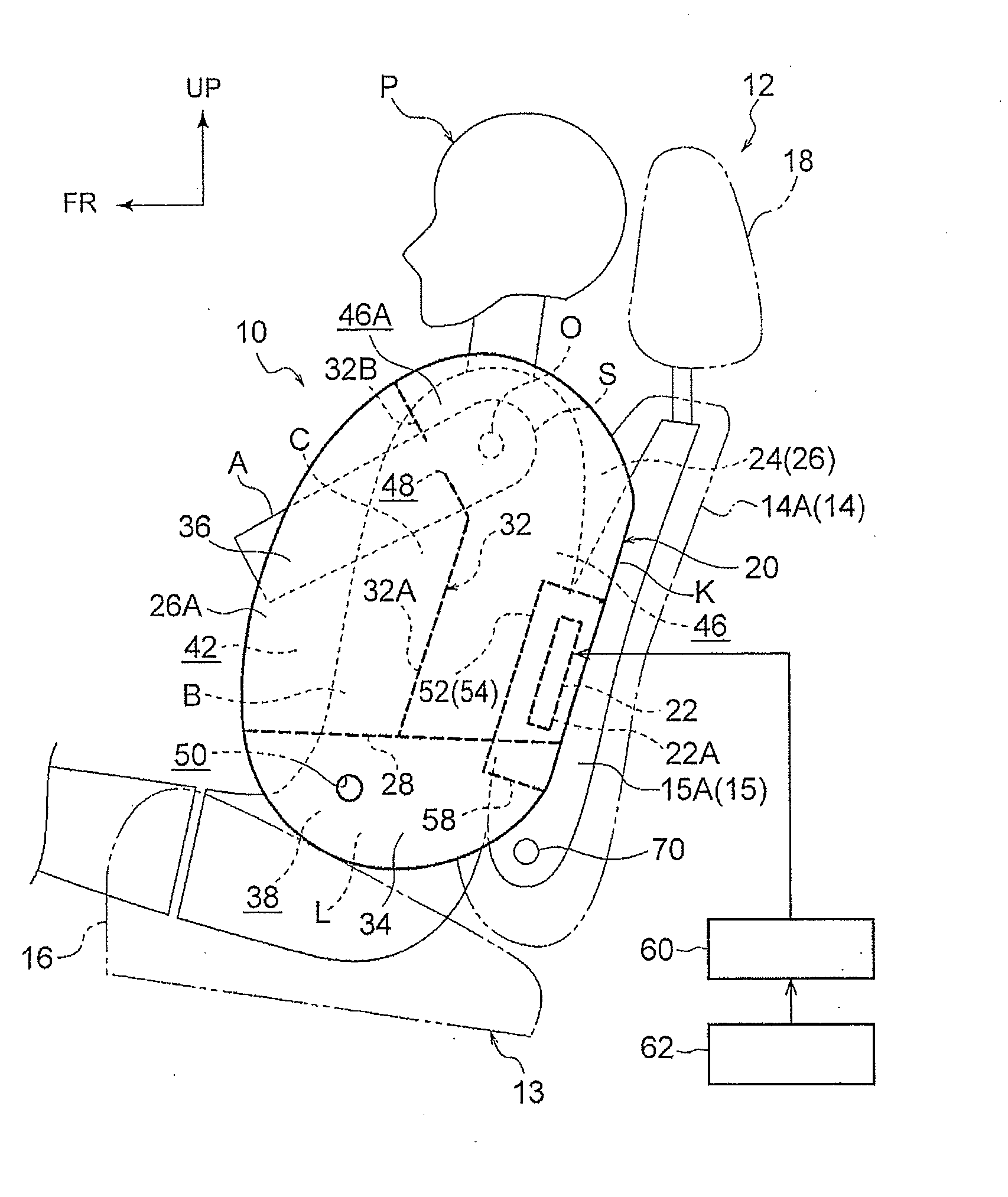
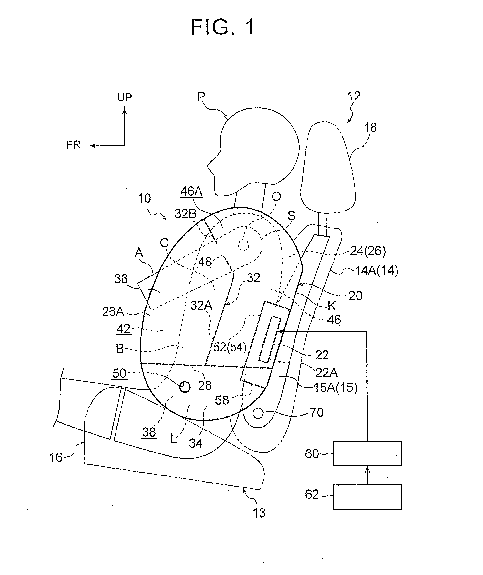
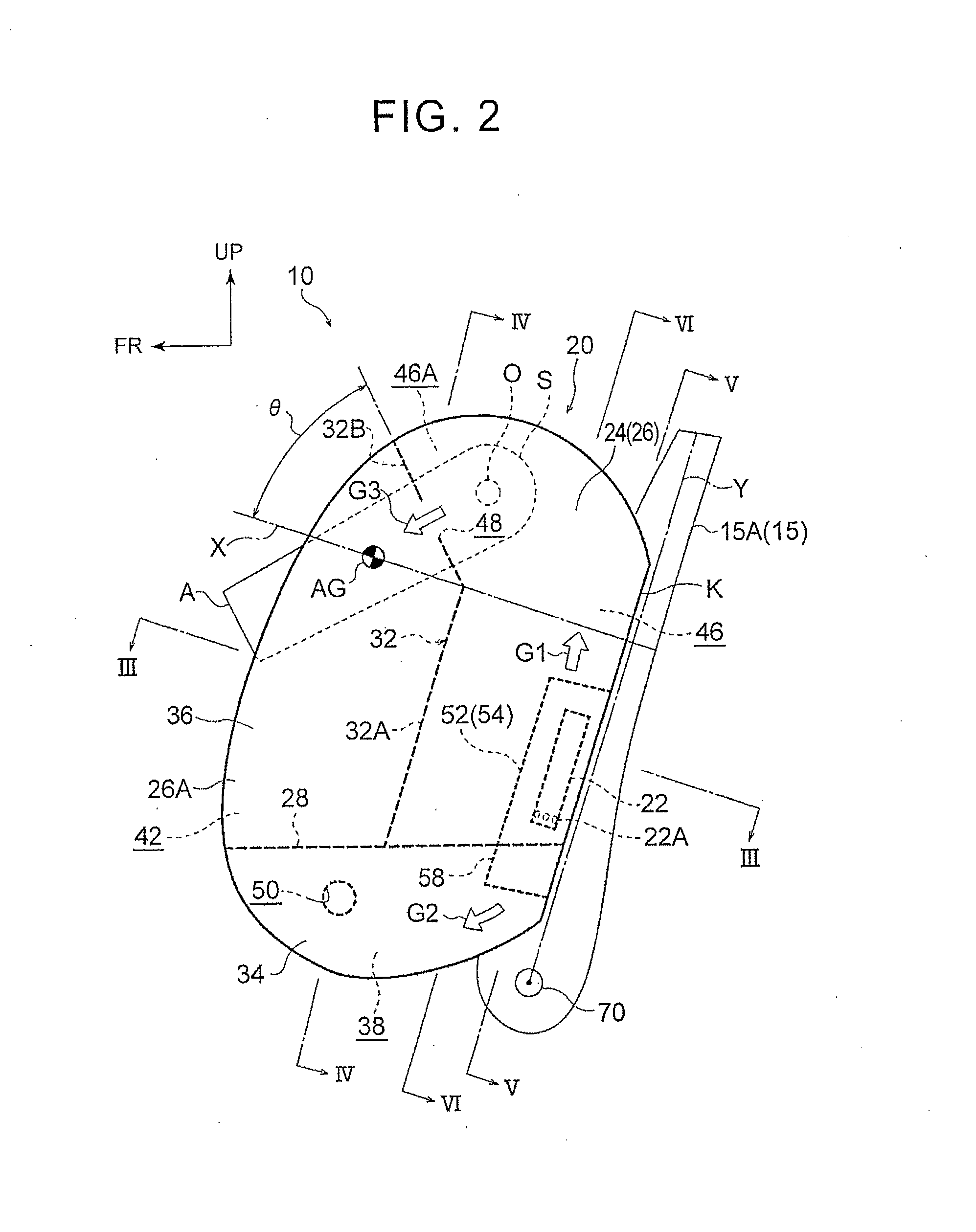
[0027]A vehicle side air bag apparatus 10 according to an embodiment of the present invention will be explained with reference to the drawings. Incidentally, an arrow FR, an arrow UP and an arrow OUT shown in each drawing appropriately respectively show a front direction (advancing direction), an upper direction and outside in a vehicle width direction. Hereinafter, unless otherwise noted, in a case where an explanation is made using merely front and rear directions, right and left directions and upper and lower directions, they refer to the front and rear in a longitudinal direction of the vehicle, the right and left in a lateral direction (width direction) of the vehicle and the up and down in a upper and lower direction of the vehicle, respectively.

(Configuration)

[0028]As shown in FIG. 1, a side air bag apparatus 10 according to this embodiment is mounted on a door-side side portion 14A of a seat back 14 in a seat main body 13 of a vehicle seat 12 (side portion at an outside in t...


PUM


Abstract

A vehicle side air bag apparatus includes: a bag that is housed within a side portion outside in a seat back in a vehicle width direction and inflates and expands to a vehicle front side of the side portion by supplying gas; an up-down partition that partitions the bag into lower and upper bag portions; a right-left partition which partitions the lower bag portion into left and right chambers, to which a right-left communication port is provided and which inhibits inflation of the lower bag portion in an upper and lower direction by being extended in the inflation and expansion state; an inflator provided in the upper bag portion; and a flow regulating portion that distributes gas into one of the left and right chambers and the upper bag portion and limits gas flow from the one chambers to the upper bag portion by a check valve portion.

Description

INCORPORATION BY REFERENCE[0001]The disclosure of Japanese Patent Application No. 2013-193435 filed on Sep. 18, 2013 including the specification, drawings and abstract is incorporated herein by reference in its entirety.BACKGROUND OF THE INVENTION[0002]1. Field of the Invention[0003]The present invention relates to a vehicle side, air bag apparatus that inflates and expands a side air bag between an occupant and a vehicle body side portion in the event of a collision of a vehicle etc. and a vehicle seat in which the vehicle side air bag apparatus is mounted.[0004]2. Description of Related Art[0005]In a side air bag apparatus disclosed in Japanese Patent Application Publication No. 2009-241643 (JP 2009-241643 A), an inner side of an air bag is vertically separated to a chest region protection portion and a lumbar region protection portion, and the lumbar region protection portion is further horizontally separated to a first lumbar region protection portion (a first compartment) and a...

Claims


Application Information

Patent Timeline
Patent Type & Authority Applications(United States)
IPC IPC(8): B60R21/231B60R21/207
CPCB60R21/23138B60R2021/23146B60R21/207B60R21/233B60R21/239
Inventor FUJIWARA, YUSUKE
Owner TOYOTA JIDOSHA KK
Why Eureka
Eureka Blog
Learn More