Inline electric generator with magnetically suspended axial flow open center impeller

a technology of axial flow and electric generator, which is applied in the direction of electric generator control, magnetic circuit shape/form/construction, magnetic circuit rotating parts, etc., can solve the problems of hydropower, pumped storage or run-of-river facilities, and long environmental impact studies, construction, licensing and regulations, and large long-term maintenance costs

Inactive Publication Date: 2015-03-19
MAGNETAR ELECTRIC TECH
View PDF22 Cites 5 Cited by
  • Summary
  • Abstract
  • Description
  • Claims
  • Application Information

AI Technical Summary

Benefits of technology

[0006]An electric power generator for placement inline with a conduit comprises a substantially cylindrical housing defining an elongated chamber configured to be coupled to the conduit so that a fluid flowing in the conduit flows through the elongated chamber, an impeller defining a central channel disposed in the elongated chamber and an inner surface of the central channel having a plurality of blade members shaping fluid flow in the central channel, where the impeller further including a matrix of permanent magnets secured to an exterior surface wall. The generator further comprises a copper coil assembly coupled to the substantially cylindrical housing and comprising a plurality of copper coils arranged circumferentially about the cylindrical housing, and configured to interact with the matrix of permanent magnets to generate electricity when the impeller rotates due to fluid flowing in the central channel and acting on the blade members.

Problems solved by technology

However, these projects, including Hydropower, Pumped Storage or Run-of-River facilities, are generally very large, costly and take years of environmental impact studies, construction, licensing and regulations and have enormous long term maintenance costs making them less appealing than other forms of renewable energy.
Today energy costs and consumption are primary concerns globally.
These mechanical systems are very inefficient, only capturing about 12-19% of the potential energy that exists within the pipe.
Due to these inefficiencies and the high costs of the equipment needed to generate this energy relative to the value of energy created, there have been no designs developed for practical low cost-effective applications of these systems.

Method used


Image

  • Inline electric generator with magnetically suspended axial flow open center impeller
  • Inline electric generator with magnetically suspended axial flow open center impeller
  • Inline electric generator with magnetically suspended axial flow open center impeller

Examples


Embodiment Construction

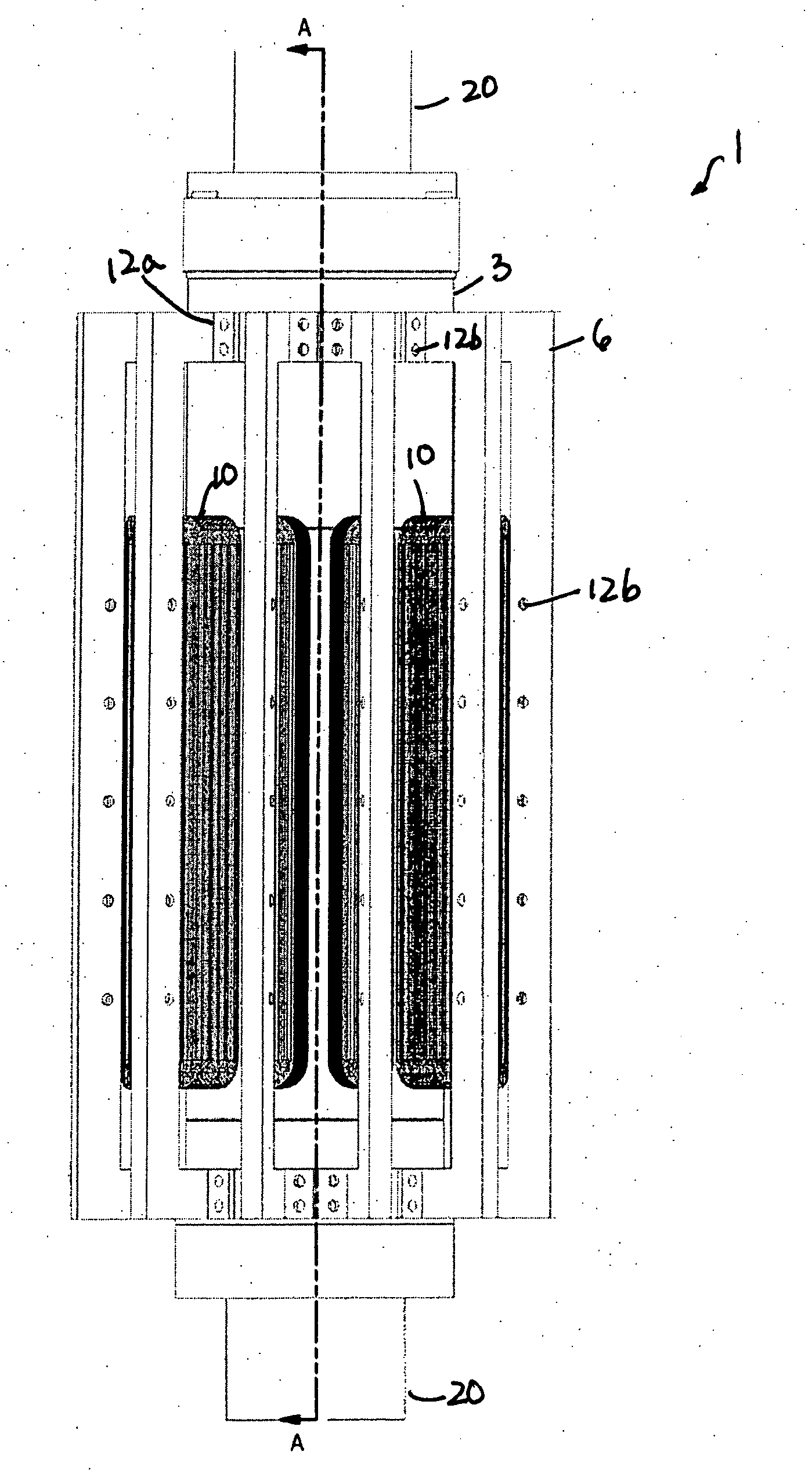
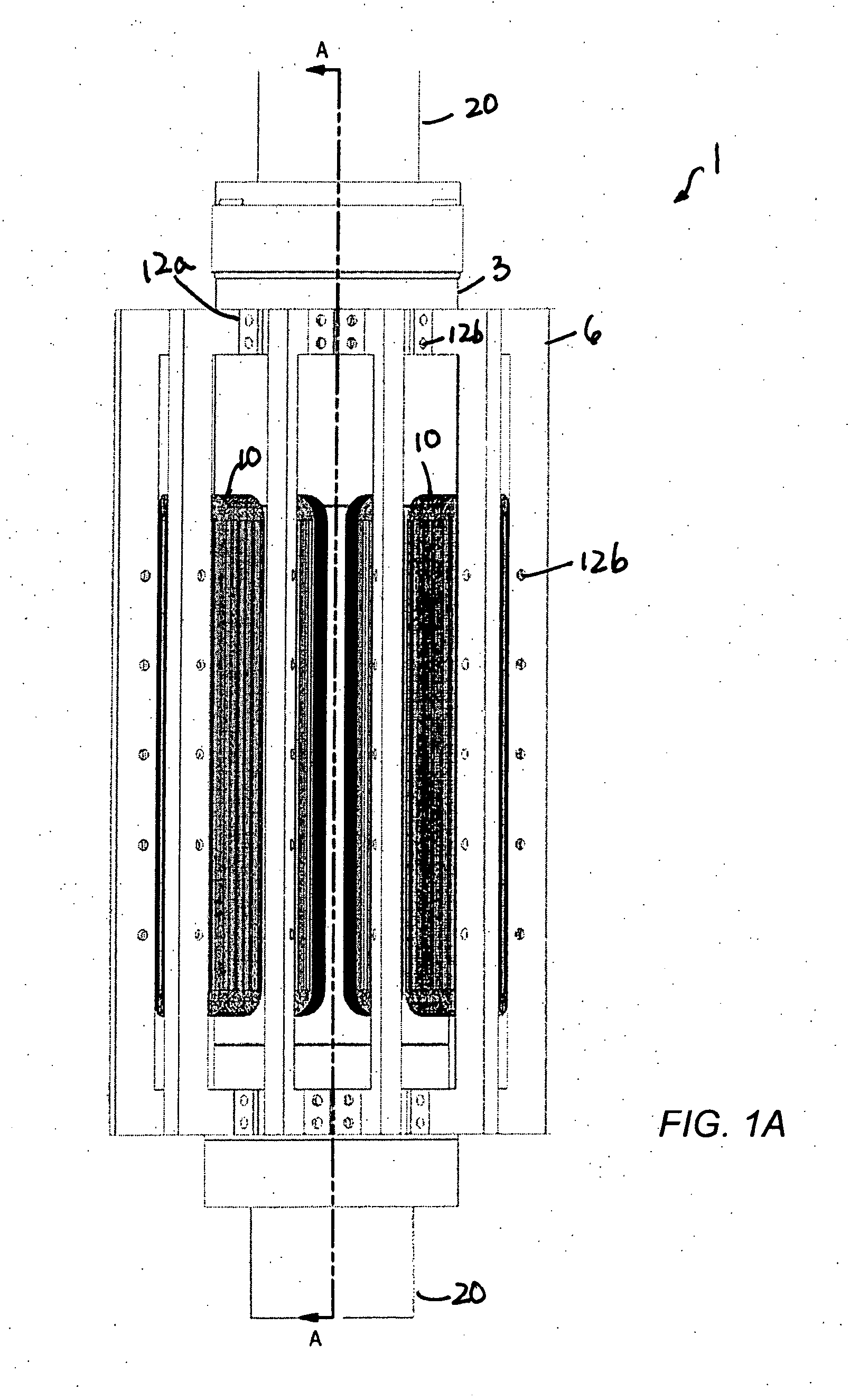
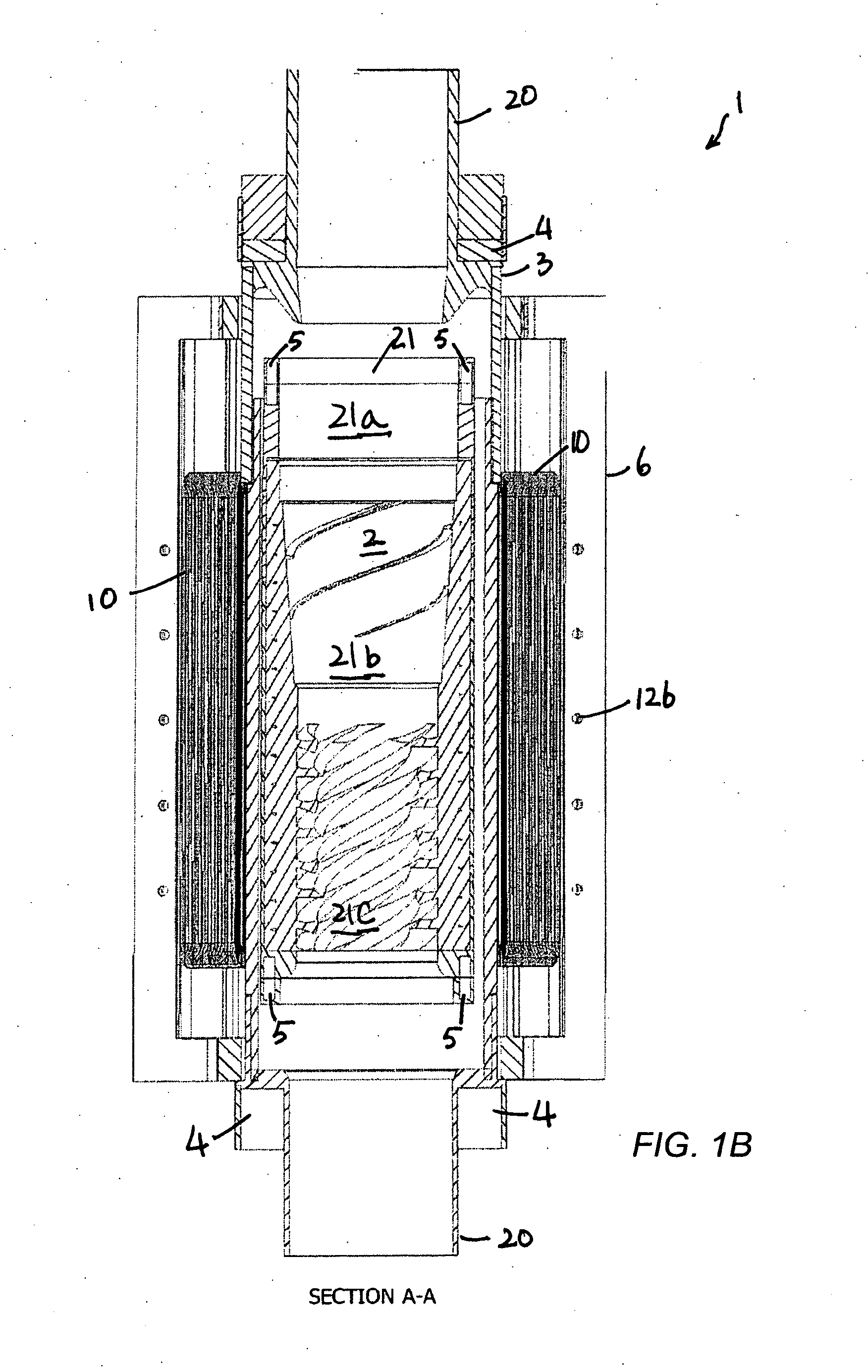
[0023]Referring now to the accompanying drawings, wherein like reference numerals designate identical or corresponding parts throughout the several views, there is illustrated an embodiment of an inline electric generating system for use in generating electricity, primarily from the kinetic energy in flowing pressurized fluids in a conduit. Other applications and embodiments are contemplated herein. As will become clear from the following description, the system embodies a number of distinct benefits over the related art, in particular a broad field of in-pipe applications, improved reliability, improved efficiency, lower costs to produce, very low maintenance and a lighter weight construction.

[0024]Referring to FIGS. 1A, 1B, and 5, the inline electric generating system 1 is generally configured for placement inline of a conduit 20 conducting a flowing fluid (gas and / or liquid). The system 1 generally includes a non-magnetic generally cylindrical housing 3 with a wall that defines a...


PUM


Abstract

An electric power generator for placement inline with a conduit comprises a substantially cylindrical housing defining a non-magnetic elongated chamber configured to be coupled to the conduit so that a fluid flowing in the conduit flows through the elongated chamber, an impeller defining a central channel disposed in the elongated chamber and an inner surface of the central channel having a plurality of blade members shaping fluid flow in the central channel, where the impeller further including a matrix of permanent magnets secured to an exterior surface wall. The generator further comprises a copper coil assembly coupled to the substantially cylindrical housing and comprising a plurality of copper coils arranged circumferentially about the cylindrical housing, and configured to interact with the matrix of permanent magnets to generate electricity when the impeller rotates due to fluid flowing in the central channel and acting on the blade members.

Description

RELATED APPLICATION[0001]The present application claims the benefit of U.S. Provisional Patent Application No. 61 / 879,043 filed on Sep. 17, 2013, incorporated herein by reference in its entirety.BACKGROUND[0002]Climate change and geopolitical concerns continue to focus our need for sources of green or renewable energy. Currently the largest investments in this technology are being made in the fields of solar and Wind technologies. Hydropower, with essentially no emissions, currently accounts for only about 7% of the electricity produced in the United States. However, these projects, including Hydropower, Pumped Storage or Run-of-River facilities, are generally very large, costly and take years of environmental impact studies, construction, licensing and regulations and have enormous long term maintenance costs making them less appealing than other forms of renewable energy.[0003]Today energy costs and consumption are primary concerns globally. Every industrial nation is currently se...

Claims


Application Information

Patent Timeline
Patent Type & Authority Applications(United States)
IPC IPC(8): H02K7/18H02K3/46H02K1/27
CPCH02K7/1823H02K3/46H02K1/2706F03B17/061H02K1/278H02K3/47H02K5/128F05B2220/20F05B2250/15Y02E10/20
Inventor WYATT, II, WILLIAM T.WYATT, JUSTIN M.
Owner MAGNETAR ELECTRIC TECH
Why Eureka
Try Eureka