Method and computer to determine a b0 field map with a magnetic resonance apparatus

a magnetic resonance and field map technology, applied in the field of method to determine a b0 field map, can solve the problems of inability to select extremely short dephasing times, ambiguities and errors in the calculation of b0 maps, and inability to measure the deviation of small deviations from the nominal larmor frequency with sufficient precision

Inactive Publication Date: 2015-03-19
SIEMENS AG
View PDF1 Cites 11 Cited by
  • Summary
  • Abstract
  • Description
  • Claims
  • Application Information

AI Technical Summary

Benefits of technology

[0025]The first solution—Equations (5a) and (6a)—of the minimization problem always yields a result of 2π. This solution is only usable for two dephasing times (echo spacings). If a third dephasing time is added, the dynamic range no longer increases. The second solution—equations (5b) and (6b)—increases the dynamic range with every additional dephasing time, and therefore offers a much greater flexibility. The use of a quotient according to the invention is therefore also preferred. However, it is noted that both solutions provide the same results for two dephasing times.
[0031]In embodiments for the approach based on first solution, given use of a product, the base time and the prime numbers of the group are chosen so that at least the desired dynamic range results as 2π divided by the base time, and at least the maximum tolerated measurement error for the phase results for the quotient of 2π and the smallest prime number of the group. For the preferred approach that is based second solution (which offers more flexibility), given use of a quotient, the base time and the prime numbers of the group are chosen so that at least the desired dynamic range results as the product of two, pi and all prime numbers of the group divided by the base time, and / or at least the maximum tolerated measurement error for the phase results for the quotient of two times pi and the largest prime number of the group.
[0032]Unambiguous boundary conditions are present that yield suitable dephasing times for the corresponding imaging task, which is defined by the (minimal) desired dynamic range and the maximum tolerable measurement errors. In the preferred case of the calculation of a quotient (Equations (5b) and the following), a base time can already result from the maximum tolerable error (which error can, however, also be considered retroactively because the essential requirement is the desired dynamic range), at which base time suitable prime numbers (and thus the group) can then easily be established. In tests, it has been shown that prime numbers that are greater than 13 are rarely actually used since sufficiently large dynamic ranges are already achieved with lower prime numbers, at least in the range of the dephasing times or echo times that are accessible anyway via gradient echo sequences. Consequently, the prime numbers of the group are chosen to be less than 17, which can be viewed as an additional boundary condition. In particular, this markedly limits the number of available prime numbers that are greater than one, such that a manageable number of possibilities is created from which suitable groups can easily be formed that satisfy the boundary conditions.

Problems solved by technology

This leads to ambiguities and errors in the calculation of the B0 maps.
The selection of extremely short dephasing times is often not possible due to the sequences that are used, wherein, given an extremely short echo time difference, smaller deviations from the nominal Larmor frequency can no longer be measured with sufficient precision.
However, since the dynamic range of the B0 field distribution is not known before the measurement, the dephasing time must be chosen to be so short that the sensitivity of the acquisition method is insufficient, and this procedure is consequently not used (as has already been presented).
However, the reliability of such algorithms is often in question.
The primary difficulty is that the entire volume can consist of non-contiguous partial regions, such that individual partial regions of the B0 maps are separated by voxels that include only noise and are very low in signal.
The phase in these voxels can thus not be determined, or can only be determined very unreliably.
However, the risk exists that a calculated B0 shim is optimized for false B0 offsets in different spatial areas.
Moreover, no frequency (shim of zeroth order) can be calculated from differential methods.
However, there is no guarantee of an actual optimal solution.

Method used


Image

  • Method and computer to determine a b0 field map with a magnetic resonance apparatus
  • Method and computer to determine a b0 field map with a magnetic resonance apparatus
  • Method and computer to determine a b0 field map with a magnetic resonance apparatus

Examples


Embodiment Construction

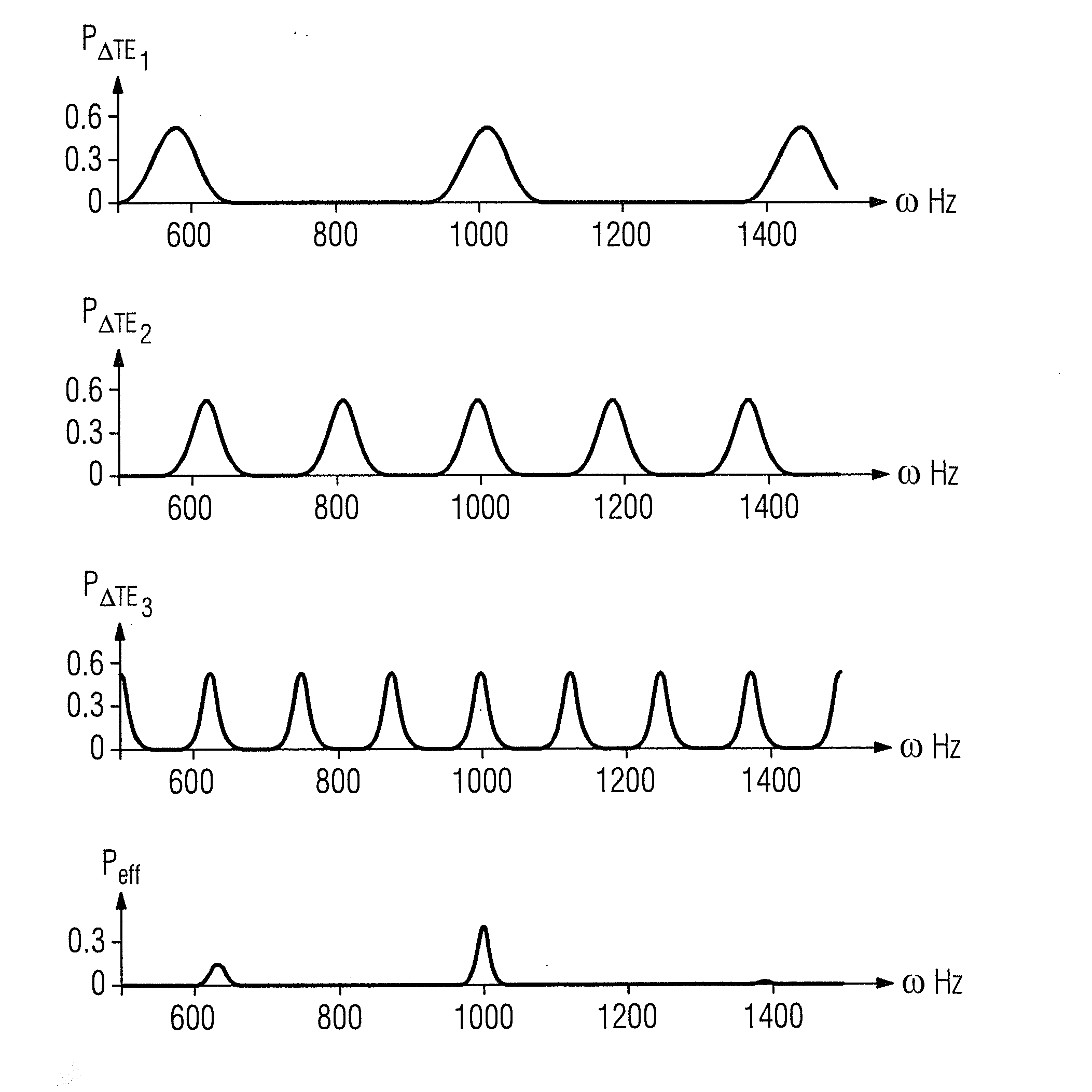
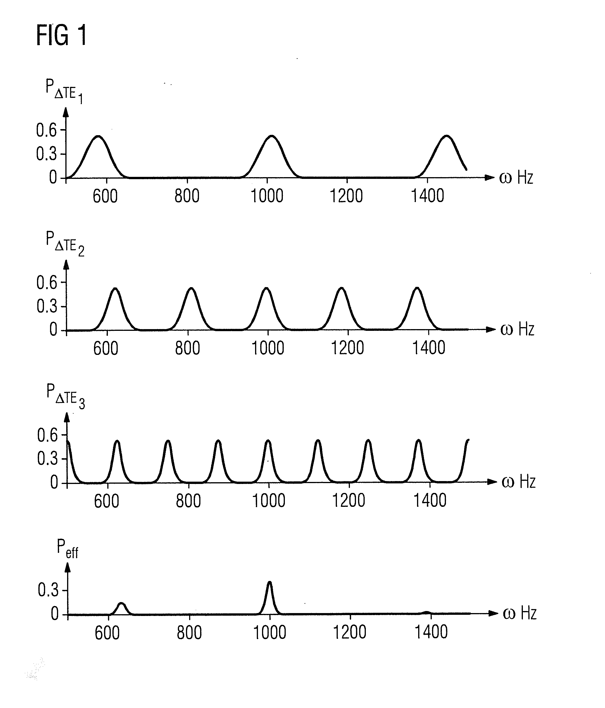
[0047]The present invention concerns the selection of suitable dephasing times given a measurement of B0 field maps using multiple different dephasing times. Ideally, an increased dynamic range should thereby be provided without losses occurring with regard to scan time and precision if it is compared with a highly precise measurement of a B0 field map with large echo spacing. Therefore, additional echoes are to be specifically selected and analytically derived echo times are measured, wherein the remaining B0 field map is reconstructed with a probability-based access. This, and the bases of the considerations, are explained in detail using FIG. 1.

[0048]In this, probability density functions PΔTEi are shown that reflect the probability that a defined frequency is the resonance frequency (Larmor frequency) of the corresponding voxel. The probability density functions clearly have a defined periodicity that is based on the Nyquist phase wrapping. The function Peff shown below in FIG. ...


PUM


Abstract

In a method to determine a B0 field map describing the local deviation of a nominal Larmor frequency of a magnetic resonance apparatus, wherein magnetic resonance data are acquired in measurements implemented at two different echo times whose difference forms a dephasing time after an excitation at at least two different dephasing times, and a phase change to be used to determine the B0 field map is determined from a difference of phases measured at different echo times, the phase changes of different dephasing times are evaluated to at least partially reduce an ambiguity due to a Nyquist phase wrapping, by using dephasing times that result as a quotient or, given the use of only two dephasing times, as a product, of a base time and a respective prime number from a group including at least two different prime numbers that are greater than one, and wherein the group is selected depending on a desired dynamic range of the B0 field map and / or a maximum tolerated measurement error for the measurements.

Description

BACKGROUND OF THE INVENTION[0001]1. Field of the Invention[0002]The invention concerns a method to determine a B0 field map describing the local deviation of a nominal Larmor frequency of a magnetic resonance apparatus, wherein magnetic resonance data are acquired at at least two different dephasing times after an excitation in measurements implemented at two different echo times whose difference forms a dephasing time, and a phase change to be used to determine the B0 field map is determined from a difference of phases measured at different echo times, wherein the phase changes of different dephasing times are evaluated to at least partially reduce an ambiguity due to a Nyquist phase wrapping. The invention also concerns a computer and a non-transitory, computer-readable data storage medium encoded with programming instructions to implement such a method.[0003]2. Description of the Prior Art[0004]Magnetic resonance imaging and its principles are widely known. A subject to be examin...

Claims


Application Information

Patent Timeline
Patent Type & Authority Applications(United States)
IPC IPC(8): G01R33/44G01R33/24G01R33/565
CPCG01R33/443G01R33/243G01R33/56563
Inventor FAUTZ, HANS-PETERGROSS, PATRICKGUMBRECHT, RENE
Owner SIEMENS AG
Why Eureka
Try Eureka