Liquid crystal display panel

a technology of liquid crystal display and display panel, which is applied in the direction of static indicating devices, instruments, non-linear optics, etc., can solve the problems of deteriorating a production capacity and a process yield of lcd panels, and achieve the effect of increasing the production capacity and reducing the process time for manufacturing

Inactive Publication Date: 2015-03-19
TCL CHINA STAR OPTOELECTRONICS TECH CO LTD
View PDF2 Cites 9 Cited by
  • Summary
  • Abstract
  • Description
  • Claims
  • Application Information

AI Technical Summary

Benefits of technology

[0018]In the LCD panel of the present invention, the test line is not required to be cut off by the laser, so as to prevent the additional laser cutting process, thereby reducing a process time for manufacturing the LCD panel as well as increasing a production capacity thereof. Therefore, the effect of the laser cutting process on the LCD panel is avoidable for ensuring a process yield of the LCD panels. Moreover, the test switches and active elements of pixels can be formed at the same time without adding additional manufacturing process.

Problems solved by technology

Since it is necessary to cut off the shorting bars by using the laser after testing the LCD panels, a laser cutting process is required, deteriorating a production capacity and a process yield of the LCD panels.

Method used


Image

  • Liquid crystal display panel
  • Liquid crystal display panel
  • Liquid crystal display panel

Examples


Embodiment Construction

[0025]The following embodiments are exemplified by referring to the accompanying drawings, for describing specific embodiments implemented by the present invention. Furthermore, directional terms described by the present invention, such as upper, lower, front, back, left, right, inner, outer, side and etc., are only directions by referring to the accompanying drawings, and thus the used directional terms are used to describe and understand the present invention, but the present invention is not limited thereto.

[0026]In the drawings, like reference numerals indicate like components or items.

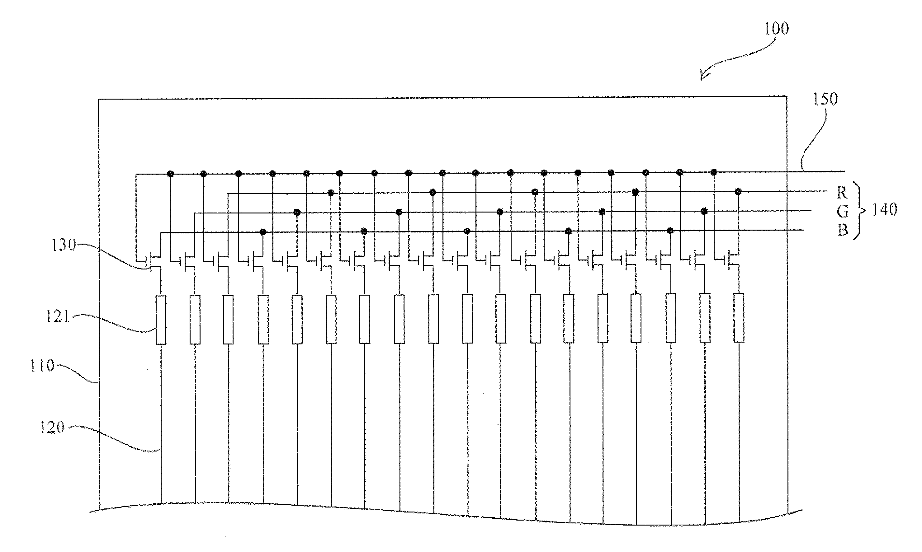
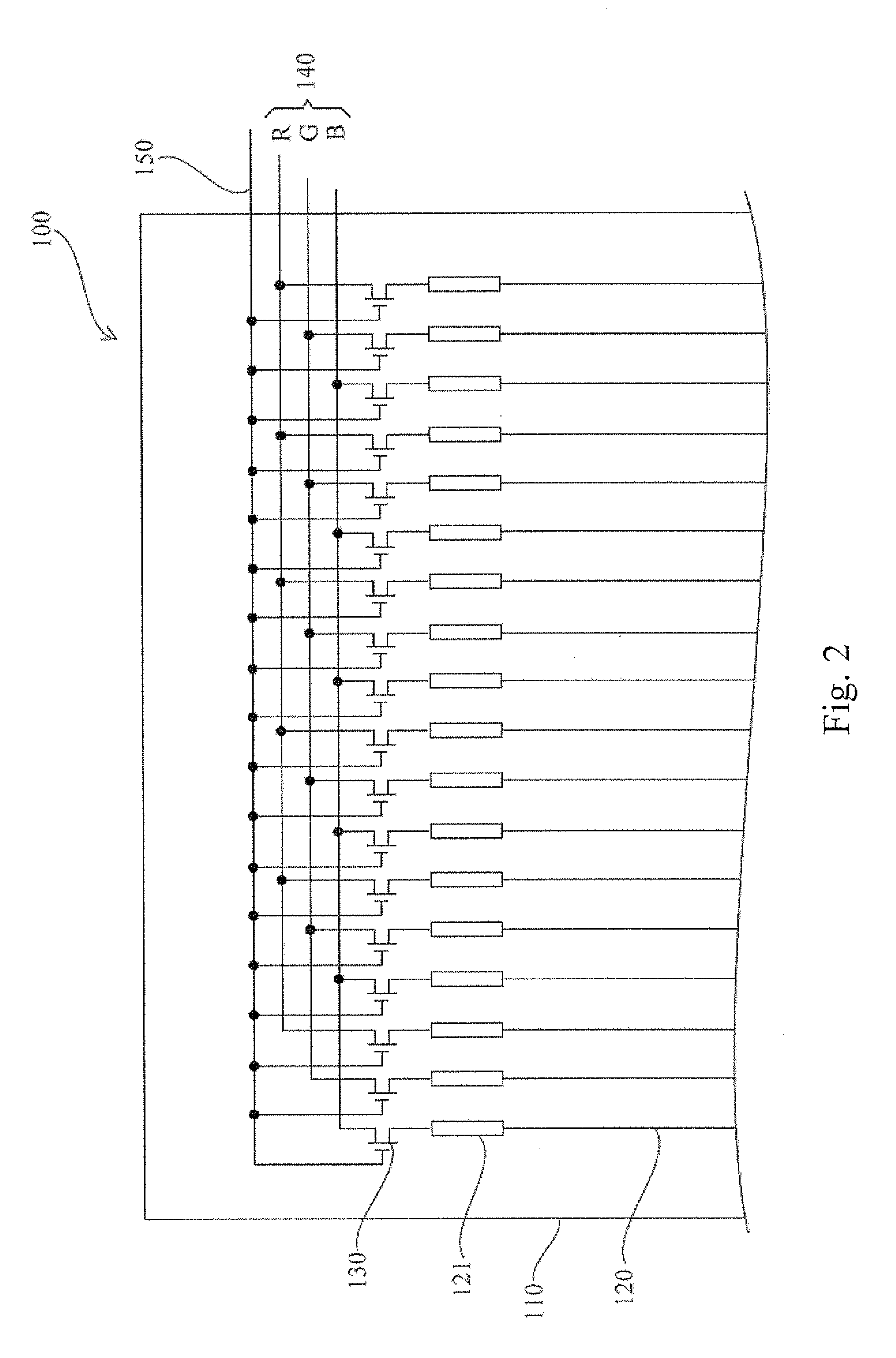
[0027]Referring to FIG. 1, a partially schematic diagram showing a liquid crystal display (LCD) panel according to a preferred embodiment of the present invention is illustrated. The LCD panel 100 and a backlight module can be assembled as an LCD apparatus. Referring to FIG. 1 again, the LCD panel 100 of the present embodiment, comprises a substrate 110 which may be a glass substrate or a flexible...


PUM

PropertyMeasurementUnit
defectsaaaaaaaaaa
process yieldaaaaaaaaaa
timeaaaaaaaaaa

Abstract

The present invention provides a liquid crystal display (LCD) panel. The LCD panel comprises a substrate, signal lines, test switches, at least one test line and a control line. The test switches are connected between the signal lines and the test line, and the at least one test line is configured to input test signals to the test switches, and the control line is configured to turn on the test switches. In the present invention, the test line is not required to be cut off by a laser, thereby improving a production capacity and a process yield of the LCD panel.

Description

FIELD OF THE INVENTION[0001]The present invention relates to a field of a liquid crystal display (LCD) technology, and more particularly to test lines of an LCD panel.BACKGROUND OF THE INVENTION[0002]LCDs have been widely applied in electrical products, wherein LCD panels are important components of the LCDs.[0003]After the LCD panels are made, in general, the LCD panels will be tested to find whether the LCD panels have defects to reduce a waste in follow-up processes. Currently, referring to FIG. 1, in the test process of the LCD panels, shorting bars 210 are disposed on an array substrate of the LCD panels and connected to signal lines 220 of the LCD panels. Test signals are inputted to the signal lines 220 through the shorting bars 210 for testing whether the signal lines are broken or have defects. After the test process, the connection between the shorting bars and the signal lines is cut off by a laser.[0004]Since it is necessary to cut off the shorting bars by using the lase...

Claims


Application Information

Patent Timeline
Patent Type & Authority Applications(United States)
IPC IPC(8): G02F1/13
CPCG02F1/1309G02F1/1362G09G3/006G09G3/36G09G2330/12G02F1/136254
Inventor LI, DONG
Owner TCL CHINA STAR OPTOELECTRONICS TECH CO LTD
Why Eureka
Try Eureka