Protective Enclosure for a Wellhead

a protection enclosure and wellhead technology, applied in the direction of keyhole guards, borehole/well accessories, building repairs, etc., can solve the problems of loss of production or supply of oil or gas flowing with the pipeline, high cost of valves and controllers, and increased installation difficulty, so as to achieve the effect of adding convenience and structural integrity

Active Publication Date: 2015-03-26
STANTON ROBERT J
View PDF4 Cites 3 Cited by
  • Summary
  • Abstract
  • Description
  • Claims
  • Application Information

AI Technical Summary

Benefits of technology

[0019]In a final version of the invention, the U-bolts used to join the individual upright legs of the panels are replaced with specially designed hinged brackets which provide added ease of installation as well as additional structural integrity to the assembly.

Problems solved by technology

Many times, a very expensive control valve may be mounted on a pipeline itself.
These valves and controllers are quite expensive, and their damage likewise brings a loss of production or supply of oil or gas flowing with the pipeline.
While this assembly of valves, tees and other fittings which is affixed to the gas well or oil well at the well head is fairly sturdy in construction, it is possible for it to become damaged in a number of different situations.
One way in which damage can occur is due to the nature of the proximity of plural wells being completed within feet of each other.
The undesirable consequence of such damage could be an uncontrolled flow of the crude oil or gas.
There have been instances, for example, where well heads have been damaged to the point of requiring replacement of one or more of the component parts.
However, the prior art proposals have generally been lacking in one or more respects.
For example, certain of the prior art constructions were permanent in nature and were not easily removed or transported from one well site to another.

Method used


Image

  • Protective Enclosure for a Wellhead
  • Protective Enclosure for a Wellhead
  • Protective Enclosure for a Wellhead

Examples


Embodiment Construction

[0031]The preferred version of the invention presented in the following written description and the various features and advantageous details thereof are explained more fully with reference to the non-limiting examples included in the accompanying drawings and as detailed in the description which follows. Descriptions of well-known components and processes and manufacturing techniques are omitted so as to not unnecessarily obscure the principle features of the invention as described herein. The examples used in the description which follows are intended merely to facilitate an understanding of ways in which the invention may be practiced and to further enable those skilled in the art to practice the invention. Accordingly, the examples should not be construed as limiting the scope of the claimed invention.

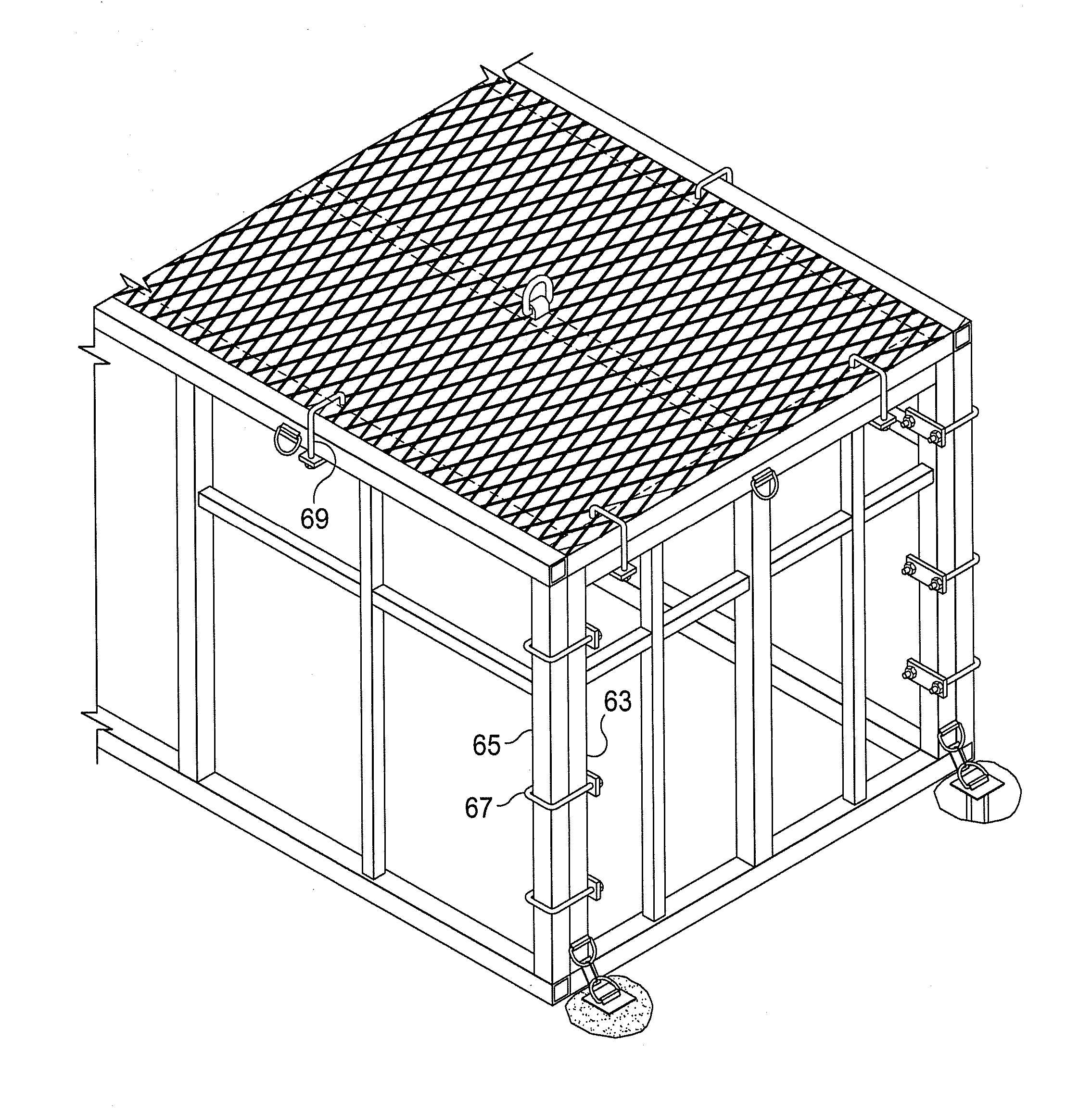
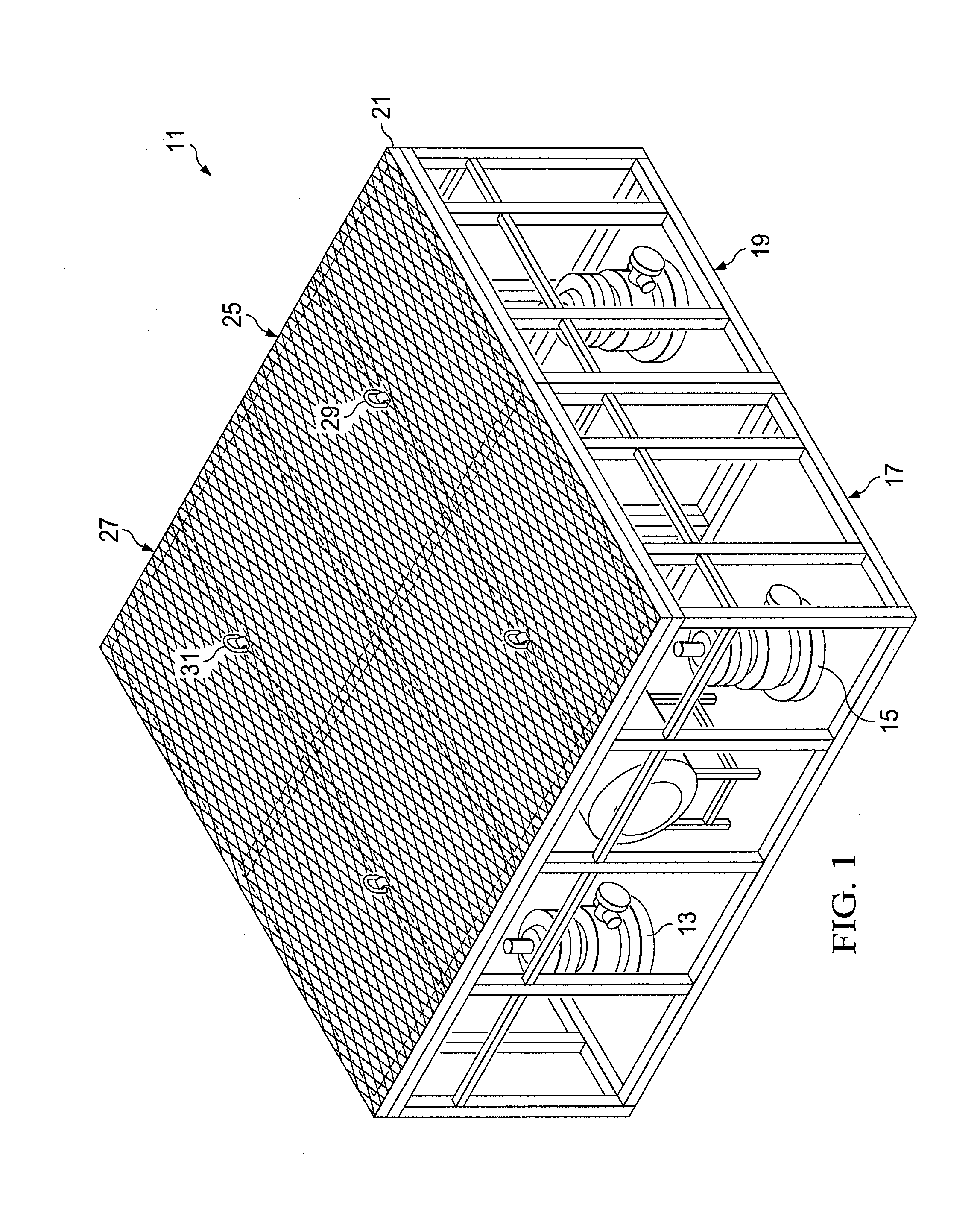
[0032]FIG. 1 is a perspective view of one version of the protective enclosure of the invention, designated generally as 11. The enclosure 11 is used to enclose a number of differen...


PUM


Abstract

A protective enclosure for protecting well head equipment at a surface location is made up of an open framework of structural members which surround and protect the well head. Individual steel panels are assembled to form a series of upstanding walls which are covered by a series of roof panels and which together define the quasi-enclosed area surrounding the well head. The roof panels are covered with a steel grating which forms a covered roof for the protective enclosure. The tubing which makes up the steel panels is spaced to allow access to the enclosed area by a worker needing to access the well head. Upright legs of the steel panels are joined together by hinged brackets. The panels can also be secured to the surrounding terrain by a cemented retainer arrangement.

Description

CROSS REFERENCE TO RELATED APPLICATIONS [0001]The present application is a continuation-in-part of earlier filed Ser. No. 13 / 893,775, filed May 14, 2013, which, in turn, was a continuation-in-part of earlier filed Ser. No. 13 / 214,380, filed Aug. 22, 2011, entitled “Protective Enclosure For A Wellhead”, by the same inventor, now abandoned.BACKGROUND OF THE INVENTION[0002]1. Field of the Invention[0003]The present invention relates generally to a system and apparatus for protecting equipment associated with oil and gas producing wells and, more specifically, for protecting exposed well head equipment such as Christmas trees, valves and accessory equipment located at the well surface.[0004]2. Description of the Prior Art[0005]The nature of the ordinary well head is such that it embodies sufficient control means that the well can be adjusted to safely produce at a desired rate. Depending on the type of formation being produced and other factors, the well head itself can assume different...

Claims


Application Information

Patent Timeline
Patent Type & Authority Applications(United States)
IPC IPC(8): E04H9/00E04D11/00E04B7/00E04C3/32E04B2/58E04B1/24
CPCE04H9/00E04B2/58E04B1/24E04B7/00E04C3/32E04B2001/5887E04B2001/2424E04B2001/2448E04B2001/246E04B2001/2463E04D11/00E05B17/2034E05B63/18E05C3/045E05B13/002E21B41/0021
Inventor STANTON, ROBERT J.
Owner STANTON ROBERT J
Why Eureka
Try Eureka