
Wave Energy Converter With Concurrent Multi-Directional Energy Absorption

Inactive Publication Date: 2015-03-26
ROHRER TECH
View PDF19 Cites 41 Cited by
  • Summary
  • Abstract
  • Description
  • Claims
  • Application Information

AI Technical Summary

Benefits of technology

The patent describes a system that uses thin, lightweight wave-front parallel surface floats to capture and utilize ocean waves. These floats are designed to be cost-effective and responsive, with the ability to self-orient. This system reduces the size and cost of the floats, making it more efficient and economical to capture energy from ocean waves. The movement of the floats is controlled by rotating arms or translating attachment linkages between the floats and a frame or other stabilizing attachment point. This technology allows for the efficient and cost-effective utilization of ocean waves for energy conversion.

Problems solved by technology

Capture efficiencies above these theoretical maximums are possible in wide wave tanks using uniform waves and conditions of “resonance” producing a wave focusing “antenna effect” but this is not achievable in real open ocean random waves.
It is generally less expensive and more reliable, however, in ocean environments to mount WEC surface floats on swing arms rather than linear tracks.

Method used


Image

  • Wave Energy Converter With Concurrent Multi-Directional Energy Absorption
  • Wave Energy Converter With Concurrent Multi-Directional Energy Absorption
  • Wave Energy Converter With Concurrent Multi-Directional Energy Absorption

Examples


Embodiment Construction

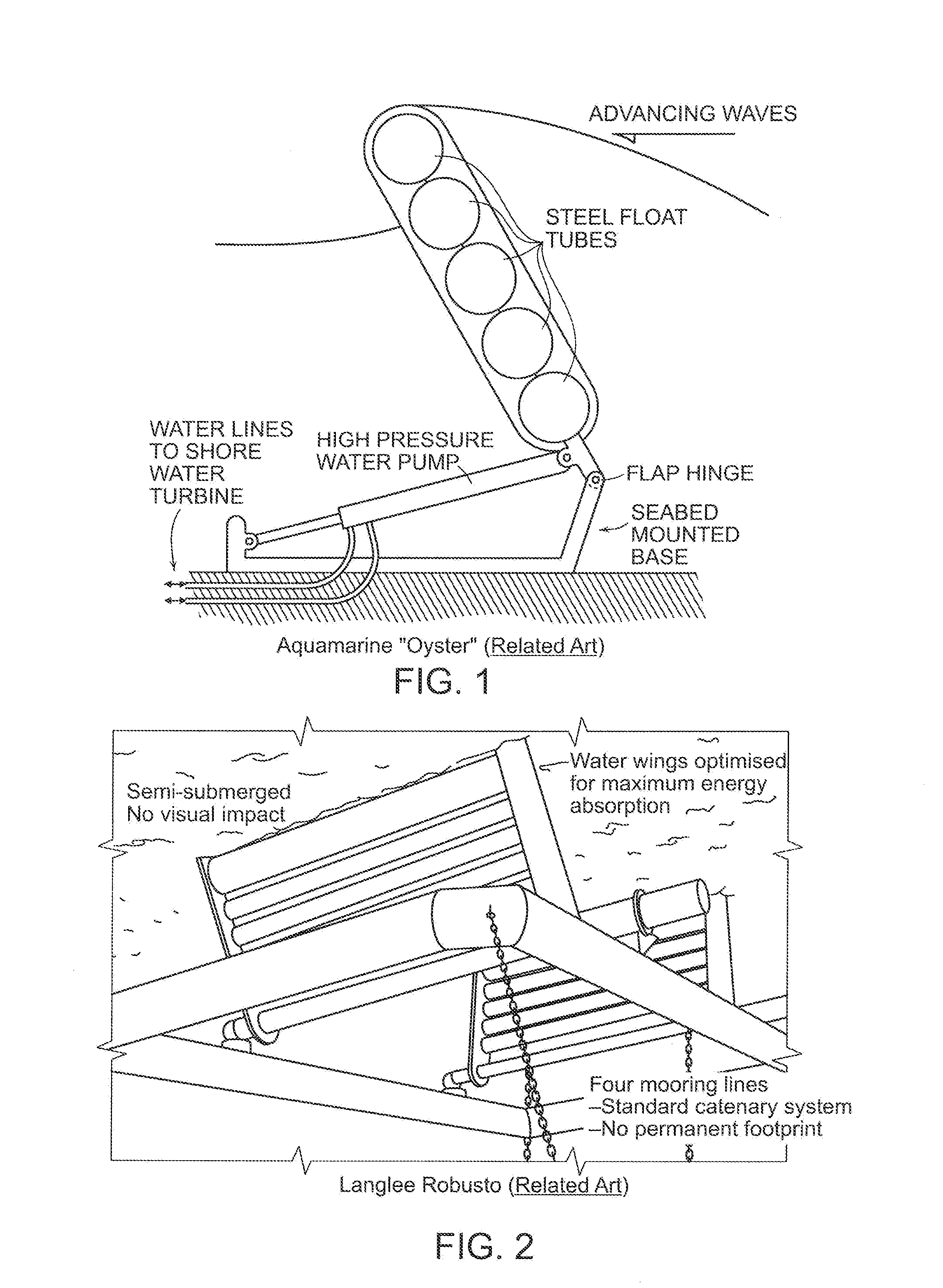
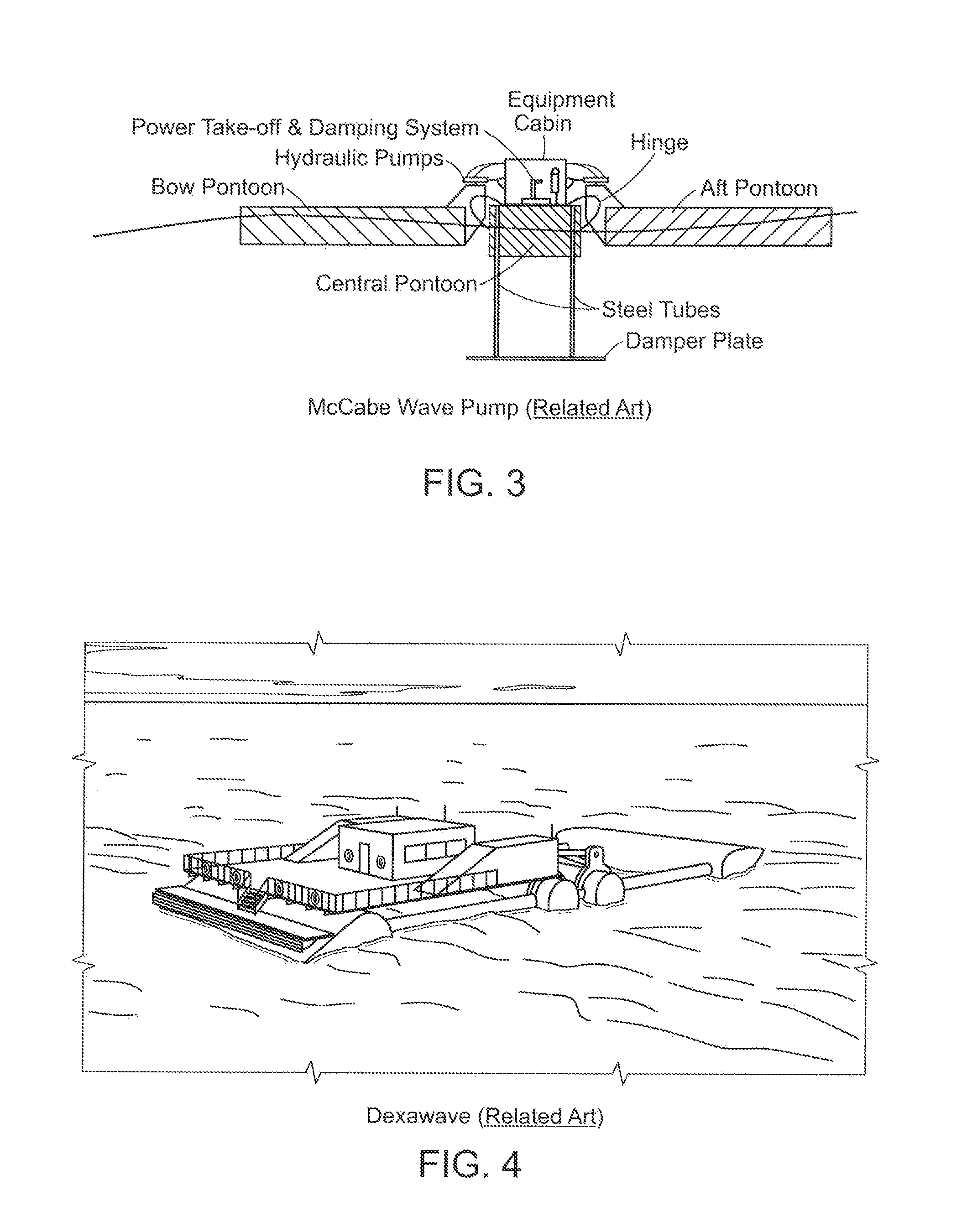
[0073]The features and limitations of the Prior Art WECs of FIG. 1 through FIG. 4, inclusively, are previously described in the previous DISTINGUISHING FEATURES OVER THE PRIOR ART section and in my U.S. Pat. No. 8,614,520 and U.S. application Ser. No. 14 / 101,325 of which this is a Continuation. The discussions of those related references are referenced here to provide perspective to the following detailed description.

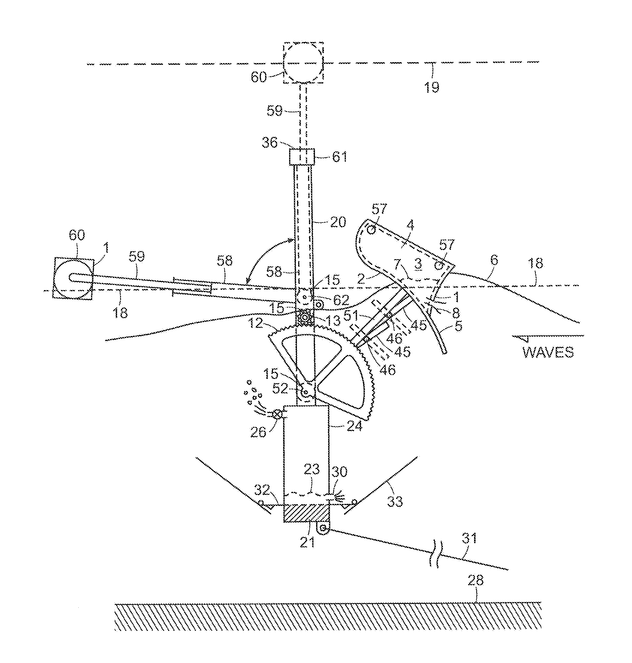
[0074]FIG. 6 is an embodiment of the present disclosure similar to FIG. 7 in application Ser. No. 14 / 101,325 wherein one or more (two shown) elongated buoyant float(s) or barrier(s), 3 and 60, having a wave front facing and impacting forward face which face may be concave (shown as 1 on the fore float 3), flat (shown as 1 on the aft float 60), or convex (not shown) and being rigid (shown), hinged (not shown) or flexible or compliant (not shown). The float(s) bottom 2 can be flat and angled approximately parallel to the float's direction or arc of motion (as in bottom 2 ...


PUM


Abstract

An ocean wave energy converter (WEC) using one or more elongated light-weight low-cost surface floats, oriented and self-orienting parallel to oncoming wave fronts are mechanically linked to a motion stabilized or fixed frame or base through one or more power take-offs in such manner that multi-directional rotational and translational wave-induced forces and relative motion between the float(s) and base are efficiently captured. Some embodiments have at least one forward positioned float that moves upward and rearward on wave crests and downward and forward on ensuing wave troughs to capture a majority of both heave and surge wave energy components. Other embodiments also provide apparatus and means to totally submerge the floats during severe seas or adjust submerged depth and float mass to optimize performance.

Description

CROSS-REFERENCE TO RELATED APPLICATIONS[0001]This is a Continuation-In-Part of U.S. Regular Utility application Ser. No. 14 / 101,325 filed Dec. 9, 2013, which is a Continuation-In-Part of U.S. Regular Utility application Ser. No. 13 / 506,680 filed May 8, 2012, now U.S. Pat. No. 8,614,520 and claims the benefit of U.S. Provisional Application Ser. No. 61 / 996,338 filed May 5, 2014, the contents all of which are incorporated in their entirety herein by reference.FIELD OF THE DISCLOSURE[0002]This disclosure relates to the production of electrical power, pressurized water, or other useful work from surface waves on a water body. More particularly, this disclosure relates to Wave Energy Converters (“WEC”) of the wave terminator or barrier type, wherein one or more elongated buoyant surface floats or bodies, or groups of adjacent floats or bodies are oriented, or self-orienting, parallel to the prevailing direction of oncoming wave fronts or swells.[0003]The disclosure relates primarily to W...

Claims


Application Information

Patent Timeline
IPC IPC(8): F03B13/16F03B13/10
CPCF03B13/10F03B13/16F03B13/182F03B13/186F05B2270/18Y02E10/30Y02E60/16
Inventor ROHRER, JOHN W.
Owner ROHRER TECH
Learn More