Gear mechanism and manufacturing method of gear mechanism

a gear mechanism and manufacturing method technology, applied in the field of gear mechanism, can solve the problems of power loss or vibration and noise due to slippage or contact between the teeth inevitably ending up, reducing power transfer efficiency or damage to the tooth face, and reducing the contact position of the tooth face, so as to reduce the hertzian stress that acts on the tooth face, the effect of suppressing or preventing the increase of friction loss

Inactive Publication Date: 2015-03-26
TOYOTA JIDOSHA KK
View PDF20 Cites 9 Cited by
  • Summary
  • Abstract
  • Description
  • Claims
  • Application Information

AI Technical Summary

Benefits of technology

[0022]According to first and second aspects of the invention, a gear in which a tooth trace is twisted at a predetermined angle with respect to an axial direction is provided, and a curvature radius along a line of contact at a meshing position where a line of contact does not intersect a pitch circle is formed larger than a curvature radius along a line of contact at a meshing position where a line of contact intersects a pitch circle, on a plane of action of the gear. Therefore, the Hertzian stress that acts on the tooth face is able to be reduced at a location where the curvature radius is formed large. Also, the friction coefficient is able to be reduced based on the length of the line of contact that becomes longer according to an increase in the curvature radius. As a result, even if the slip speed on the line of contact increases due to the length of the line of contact increasing, an increase in friction loss can be suppressed or prevented, or friction loss can be reduced.
[0023]Also, a curvature radius along a line of contact at a meshing position at which a percentage by which an integrated value of a slip speed on a line of contact increases due to lengthening the line of contact is larger than a percentage by which a friction coefficient decreases due to lengthening the line of contact, may be larger than a curvature radius along a line of contact at a meshing position at which a percentage by which an integrated value of a slip speed on a line of contact increases due to lengthening the line of contact is smaller than a percentage by which a friction coefficient decreases due to lengthening the line of contact. Therefore, it is possible to increase only the curvature radius at a meshing position where the friction loss will not increase even if the length of the line of contact is not increased, and as a result, the Hertzian stress that acts on the tooth face can be reduced without increasing the friction loss or while reducing the friction loss.
[0024]Furthermore, the percentage by which the friction coefficient decreases due to lengthening the line of contact may be large when a surface texture or a surface roughness of the tooth face of the gear is good, and may be small when the surface texture and the surface roughness of the tooth face of the gear is poor, so the position that increases the line of contact is able to be changed based on the surface texture and the surface roughness. As a result, the Hertzian stress that acts on the tooth face can be reduced without further increasing the friction loss or while reducing the friction loss.
[0025]Also, the curvature radius includes a relative curvature radius calculated based on the curvature radius along a line of contact of each of the pair of gears, so an increase in friction loss can be suppressed or prevented, or friction loss can be reduced, and the Hertzian stress can be reduced, without excessively increasing the curvature radius of each gear.
[0026]Further, manufacturing the gear mechanism by forging enables the forming cost for forming the tooth surface configuration, and the man-hours for machining to be reduced.

Problems solved by technology

Gear mechanisms transmit power by the intermeshing of teeth, so when the teeth of one gear mesh with the teeth of another gear, or when power is transmitted while the meshing position changes, power loss or vibration and noise due to slippage or contact between the teeth inevitably ends up occurring.
However, because the gear rotates and transmits power while changing the contact position, slippage inherently occurs at the contact position of the tooth face.
This slippage results in friction loss, which may result in reduced power transfer efficiency or damage to the tooth face.

Method used


Image

  • Gear mechanism and manufacturing method of gear mechanism
  • Gear mechanism and manufacturing method of gear mechanism
  • Gear mechanism and manufacturing method of gear mechanism

Examples


Embodiment Construction

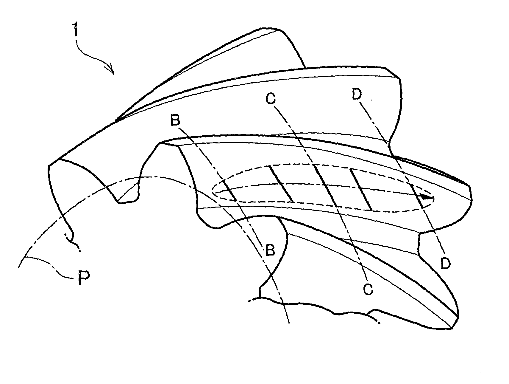
[0040]First, the basic structure of a gear to which the gear mechanism according to an embodiment of the invention may be applied will be briefly described with reference to FIGS. 5 and 6. The gear mechanism according to an embodiment of the invention may be applied to a gear 1 such as a helical gear or double helical gear or a worm gear shown in FIG. 5, in which a line of intersection of a tooth face 2 and a pitch surface 3 of the gear 1, i.e., a tooth trace 4, is twisted (i.e., skewed) at a predetermined angle (hereinafter, referred to as “twist angle θ”) with respect to an axial direction. That is, the gear mechanism of the invention may be applied to a gear in which the teeth are formed continuously twisted in the circumferential direction along a central axis s. The pitch surface 3 is a cylindrical surface where gears that transmit power contact each other as they rotate. Therefore, when the position where the gears contact each other is on the pitch surface 3, slippage does no...


PUM

PropertyMeasurementUnit
curvature radiusaaaaaaaaaa
relative curvature radiusaaaaaaaaaa
friction coefficientaaaaaaaaaa

Abstract

In a gear mechanism that includes a gear in which a tooth trace is twisted at a predetermined angle with respect to an axial direction, a curvature radius along a line of contact at a meshing position where a line of contact does not intersect a pitch circle is formed larger than a curvature radius along a line of contact at a meshing position where a line of contact intersects a pitch circle, on a plane of action of the gear.

Description

BACKGROUND OF THE INVENTION[0001]1. Field of the Invention[0002]The invention relates to a gear mechanism that transmits power by the intermeshing of teeth. More particularly, the invention relates to a gear mechanism provided with a gear in which a tooth trace is twisted at a predetermined angle with respect to an axial direction, and to a manufacturing method of this gear mechanism.[0003]2. Description of Related Art[0004]Gear mechanisms are used in a variety of machines to change the direction of rotation of the axis of rotation of transmitted power, or to change the rotation speed of the power, or to change the torque. Gear mechanisms transmit power by the intermeshing of teeth, so when the teeth of one gear mesh with the teeth of another gear, or when power is transmitted while the meshing position changes, power loss or vibration and noise due to slippage or contact between the teeth inevitably ends up occurring.[0005]Japanese Patent Application Publication No. 2008-275060 (JP...

Claims


Application Information

Patent Timeline
Patent Type & Authority Applications(United States)
IPC IPC(8): F16H55/08B21K1/30
CPCB21K1/305F16H55/08F16H55/0886Y10T74/19953Y10T29/49474
Inventor OKAMOTO, DAISUKE
Owner TOYOTA JIDOSHA KK
Why Eureka
Try Eureka