Coupling device of a switchable cam follower of a valve train of an internal combustion engine

a technology of internal combustion engine and cam follower, which is applied in the direction of valve arrangement, machines/engines, mechanical equipment, etc., can solve the problems of relative complexity of construction, high assembly cost, and risk that at least one of the components could loose in an undesired way

Inactive Publication Date: 2009-12-31
SCHAEFFLER TECH AG & CO KG
View PDF7 Cites 0 Cited by
  • Summary
  • Abstract
  • Description
  • Claims
  • Application Information

AI Technical Summary

Benefits of technology

[0014]In addition it is provided to let the contact for the support element directly intersect the pressure space section by section. Thus,

Problems solved by technology

Disadvantages are their relatively complicated construction and also their expensive assembly processes.
It has also been determined that in a

Method used


Image

  • Coupling device of a switchable cam follower of a valve train of an internal combustion engine
  • Coupling device of a switchable cam follower of a valve train of an internal combustion engine

Examples


Embodiment Construction

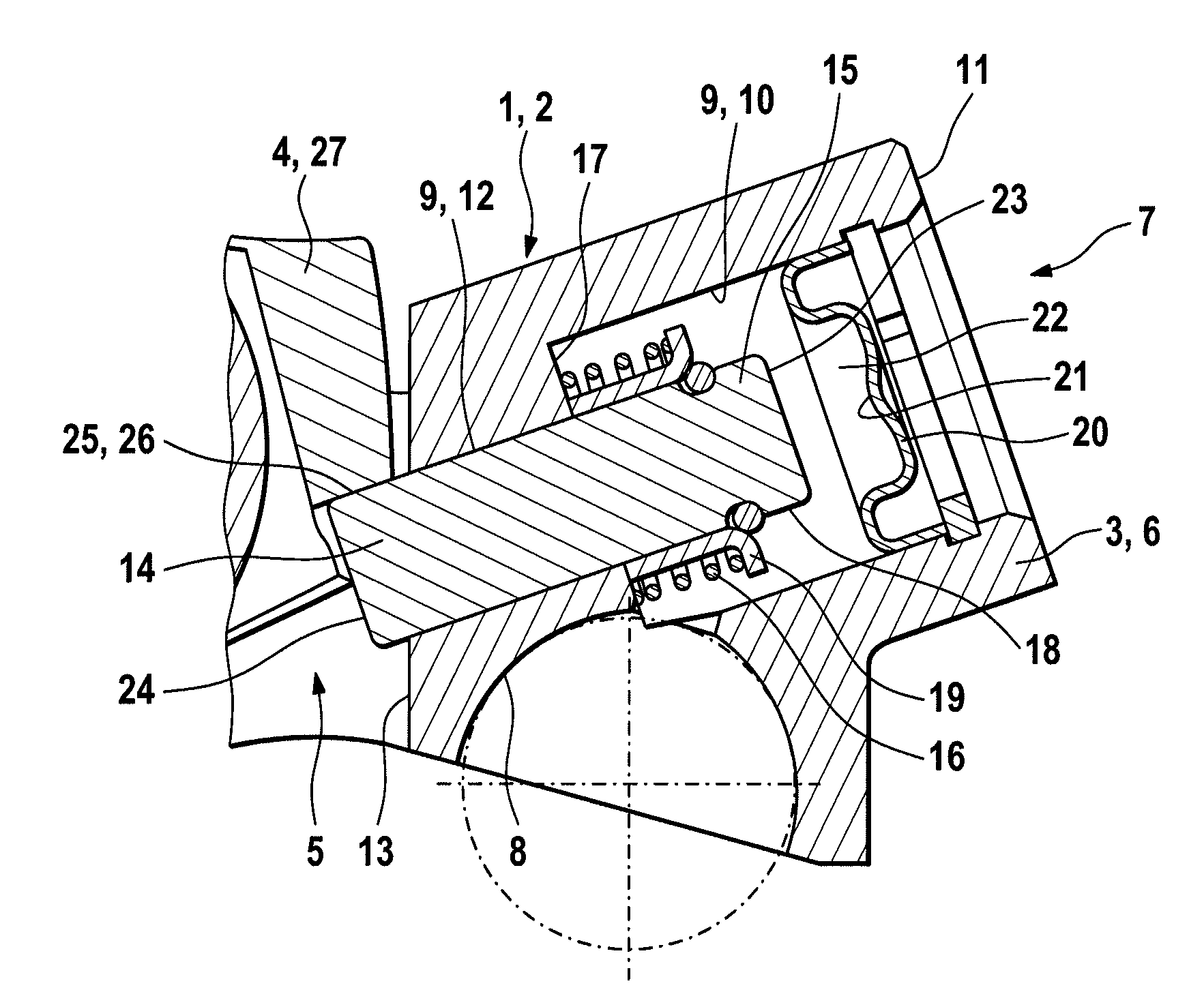
[0018]The figures show a switchable cam follower 2 in the region of its coupling device 1. One end 7 is shown on which a dome-shaped contact 8 for a support element runs in an outer lever 3 on a bottom side 5. On the not-shown, opposing end, on the bottom side 5, the cam follower 2 acts on a gas-exchange valve in a lifting sense. An inner lever 4 that is enclosed by arms of the outer lever 3 extends in the region of the latter end on a common axis with the outer lever 3. Both levers 3, 4 can move in a pivoting motion relative to each other.

[0019]The outer lever 3 has, on the shown end 7, a crosspiece 6. A stepped borehole 9 extends in this piece. The latter has a first section 10 of large diameter and a second section 12 of accordingly smaller diameter. The section 10 is bored directly from an outer side 11 of the crosspiece 6 and transitions after an annular end 17 into the second section 12. In the latter runs a smooth cylindrical, that is, non-stepped coupling slide 14 that proje...


PUM


Abstract

A coupling device (1) of a switchable cam follower (2), in which a borehole (9) extends above a contact (8) for a support element in an outer lever (3) of the cam follower (2), and this borehole has a first section (10) of large diameter that starts from an outer side (11) of a crosspiece (6) on the other end (7) to which connects to a second section (12) of accordingly smaller diameter up to directly before an inner side (13) of the crosspiece (6). A smooth cylindrical coupling slide (14) is guided in a sealing manner through the second section (12), and this coupling slide projects with a sub-region (15) into the first section (10). This sub-region (15) is encompassed by a compression spring (16) that acts, on one end, against an annular end (17) formed between the sections (10, 12) and, on the other end, against a catch element (19) arranged on the lateral surface (18) of the sub-region (15). The first section (10) is closed by a thin-walled plug (20), such that a pressure space (22) for hydraulic medium is located axially between the annular end (17) of the borehole (9) and an inner side (21) of the plug (20), and for a coupled case, the coupling slide (14) can be brought into contact by hydraulic medium that can be guided into the pressure space (22) before its outer end (23) with a sub-region (25) extending on its inner end (24) with a catch surface (26) of a cross region (27) of the inner lever (4) and, for a decoupled case, the coupling slide (14) can be displaced in the direction toward the plug (20) such that it is out of contact from the catch surface (26) for a switched-off/reduced hydraulic medium pressure via the compression spring (16).

Description

CROSS-REFERENCE TO RELATED APPLICATIONS[0001]This application claims the benefit of German patent application no. 10 2008 030 794.7, filed Jun. 28, 2008, which is incorporated herein by reference as if fully set forth.BACKGROUND[0002]The invention relates to a coupling device of a switchable cam follower of a valve train of an internal combustion engine, wherein this cam follower has an outer lever with an inner lever running between its arms and also, on its bottom side, a single-end contact for a gas-exchange valve, wherein, on this end, the levers move on an axis in a pivoting motion relative to each other, wherein a dome-shaped contact for a support element is inherent in the outer lever on a crosspiece on the other end and at least one of the levers has a cam run-on surface, wherein the coupling device in the outer lever consists of a borehole above the contact, wherein, for a coupled case [large valve stroke], the coupling slide can be brought into contact using a hydraulic me...

Claims


Application Information

Patent Timeline
IPC IPC(8): F01L1/12
CPCF01L13/0005F01L1/185
Inventor SEITZ, JOACHIMKRAUSE, JOACHIMLANG, JENS
Owner SCHAEFFLER TECH AG & CO KG
Why Eureka
Try Eureka