Directional or flow control valve

a flow control valve and directional or flow control technology, applied in the direction of process and machine control, instruments, transportation and packaging, etc., can solve the problems of correspondingly reducing the performance of the directional or flow control valve, and achieve the effect of reducing the flow resistan

Inactive Publication Date: 2007-08-30
ROBERT BOSCH GMBH
View PDF11 Cites 28 Cited by
  • Summary
  • Abstract
  • Description
  • Claims
  • Application Information

AI Technical Summary

Benefits of technology

[0012]The valve is particularly simple to manufacture if the slide is guided in a slide bushing that is inserted into a valve bore of the valve housing and in some regions, delimits the control edges, the annular chamber, the annular conduit, and the at least one diagonal bore.
[0015]In a simplified embodiment, the pressure compensator spool is guided directly in the housing of the valve, thus making it possible to eliminate a separate guide bushing for the pressure compensator spool.

Problems solved by technology

In this design, it is disadvantageous that in the region ot the star-shaped arrangement of bores, instances of relatively high flow resistance occur so that this directional or flow control valve has a correspondingly reduced performance.

Method used


Image

  • Directional or flow control valve
  • Directional or flow control valve
  • Directional or flow control valve

Examples


Embodiment Construction

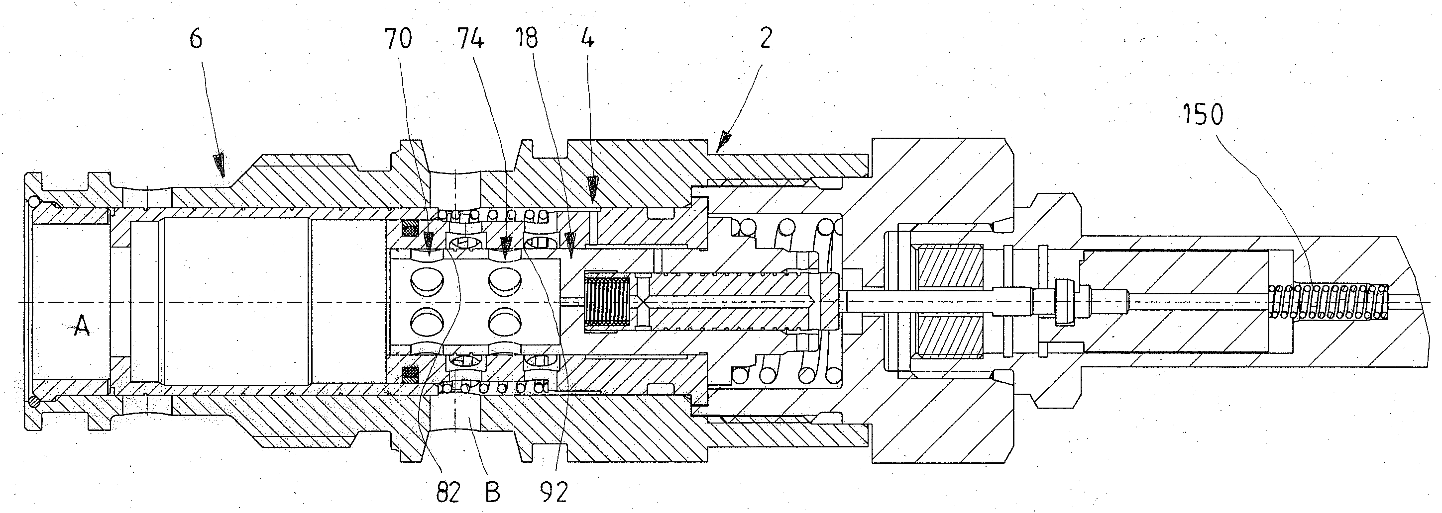
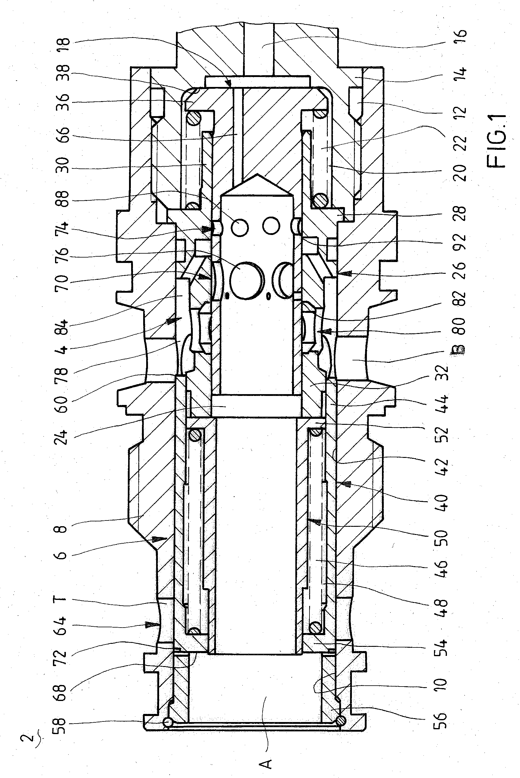
[0033]FIG. 1 shows a longitudinal section through a hydraulic 3-way flow control valve 2 that has an adjustable metering orifice 4 and a pressure compensator 6, which is connected downstream of the metering orifice 4, that combine to form a flow regulator that can keep the pressure drop due to the metering orifice 4 constant, independent of the load pressure, temperature fluctuations, and pressure fluctuations at the inlet connection A and outlet connection B.

[0034]The flow control valve 2 has a multipart valve housing 8 with an axial valve bore 10 that has a radial expansion 12 on the right in the view shown in FIG. 1. In the region of the radial expansion 12, the valve housing 8 encompasses a fastening section 14 and is screw-connected to it. In the fastening section 14, a tappet bore 16 is provided to accommodate a tappet, not shown, of a proportional magnet provided to move a metering orifice slide 18 of the metering orifice 4. The tappet bore 16 opens out into a radially enlarg...


PUM


Abstract

A valve selected from the group consisting of a directional valve and a flow control valve has an inlet connection, an outlet connection, a slide that controls a fluid connection between the inlet connection and the outlet connection, the slide being configured so that it controls the fluid connection in at least two adjustable opening cross-sections that are spaced axially apart from each other and allow a partial flow to pass through.

Description

CROSS-REFERENCE TO A RELATED APPLICATION[0001]The invention described and claimed hereinbelow is also described in German Patent Application DE 110 2006 034 366.2 filed on This German Patent Application, whose subject matter is incorporated here by reference, provides the basis for a claim of priority of invention under 35 U.S.C. 119(a)-(d).BACKGROUND OF THE INVENTION[0002]The invention relates to a directional or flow control valve.[0003]The invention can generally be used in valves for adjusting a flow of pressure fluid, particularly in 2-way valves or continuously adjustable orifices. An important application field includes flow control valves that can keep a set flow rate constant independent of pressure fluctuations. This is achieved by virtue of the fact that an adjustable metering orifice is associated with a pressure compensator, which is acted on in the opening direction by both the force of a spring and a pressure downstream of the metering orifice and is acted on in the c...

Claims


Application Information

Patent Timeline
Patent Type & Authority Applications(United States)
IPC IPC(8): F15B13/043
CPCG05D7/0133Y10T137/86799Y10T137/86614G05D7/005
Inventor IMHOF, RAINER
Owner ROBERT BOSCH GMBH
Why Eureka
Try Eureka