Sweeping and twisting type three-dimensional blade diffuser and design method thereof

A three-dimensional vane and diffuser technology, which is applied in mechanical equipment, non-variable pumps, machines/engines, etc., can solve the problem of decreased diffuser capacity, reduced diffuser working range, and low-velocity areas on the pressure surface To achieve the effects of improving flow, eliminating airflow separation and load loss on the blade surface, and eliminating shock waves

Active Publication Date: 2014-05-07
NANJING UNIV OF AERONAUTICS & ASTRONAUTICS
View PDF4 Cites 29 Cited by
  • Summary
  • Abstract
  • Description
  • Claims
  • Application Information

AI Technical Summary

Problems solved by technology

The large positive angle of attack near the blade tip will lead to the separation of the airflow on the suction surface, and this situation will increase the degree of constriction from the inlet to the throat near the blade tip, and the local acceleration of the suction surface will cause strong shock waves, and the strong shock waves and the boundary layer Interference causes separation, and the generation and development of separation lead to a decrease in the diffuser's diffusion capacity and an increase in flow loss, which also reduces the working range of the diffuser; a large negative angle of attack near the blade root will cause a low-velocity zone on the pressure surface or even separation, resulting in a loss of load

Method used


Image

  • Sweeping and twisting type three-dimensional blade diffuser and design method thereof
  • Sweeping and twisting type three-dimensional blade diffuser and design method thereof
  • Sweeping and twisting type three-dimensional blade diffuser and design method thereof

Examples


Embodiment

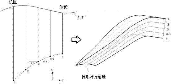
[0054] 1) Determine the overall size of the diffuser, including the inlet diameter of 300mm, the inlet blade height of 15mm, the maximum diameter of 450mm and the axial length of 95mm, and design the shape of the meridian flow channel. Divide the meridian channel of the diffuser into seven sections along the span direction (blade height direction).

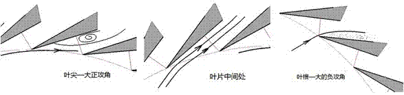
[0055] 2) Given that the sweep angle is a constant value of 15° along the span direction, that is, forward sweep, the inlet diameter of the third section (middle section) is the design value of 300mm, combined with the inlet blade height of 15mm, the inlet leading edge curve can be determined (such as attached image 3 Middle left panel, where the grazing angle α =15°, section n=7), and then determine the inlet diameter of section 1~7 d 1 ~ d 7 .

[0056] 3) Determine the channel angles at the inlets of the seven sections according to the distribution law of the incoming airflow angle along the span direction β 1 ~ β 7 (...


PUM


Abstract

The invention relates to a sweeping and twisting type three-dimensional blade diffuser. According to the structure, the front edges of blades are designed into a sweeping shape, the sweeping angle ranges from -45 degrees to 45 degrees, and the blades are suitable for incoming flow and are twisted to be expanded into different air flow angles. The main blade is designed into a three-dimensional integral structure from an inlet to an outlet in the axial direction. The flow-dividing blades are arranged on the rear section in a main blade channel. The sweeping and twisting type three-dimensional blade diffuser has the advantages that interaction of shock waves and a boundary layer is relieved, so that flow in the diffuser is modified; blade surface air flow separation and load loss which are caused by a relative large positive/negative attack angle in part of the blades in the high portion are eliminated, flow loss is reduced, and therefore a stator part diffuser of a centrifugal/oblique flow gas compressor can reach the higher efficiency and the larger pressure ratio. The strength of the shock waves is changed and the shock waves are even eliminated and influence caused by interaction of the shock waves and the boundary layer is relieved; flow loss caused by the overlarge positive attack angle or the overlarge negative attack angle is avoided, the expansion capacity and the operation range of the diffuser are improved, and therefore the improvement in the performance of the whole-level gas compressor is assisted.

Description

technical field [0001] The present invention relates to a centrifugal or oblique-flow compressor's swept-twisted three-dimensional vane diffuser and its design method, which can adapt to the non-uniform transonic inflow condition in the span direction, reduce the flow loss in the diffuser, and make the compressor reach Higher efficiency and pressure ratio belong to the technical field of radial flow compressors. Background technique [0002] Over the past half a century, the power plant has been continuously developed, and the power-to-weight ratio has been continuously increased. At the same time, it is required to minimize the number of components and reduce the size of the components to reduce weight. This requires increasing the single-stage pressure ratio of the centrifugal (or diagonal flow) compressor. Under the existing requirements for increasing the pressure ratio of the centrifugal compressor, the Mach number at the inlet of the diffuser will reach about 1.0, and ...

Claims


Application Information

Patent Timeline
Patent Type & Authority Applications(China)
IPC IPC(8): F04D29/44F04D29/40
Inventor 陈杰张晓瑜雷王兴马文孝黄国平
Owner NANJING UNIV OF AERONAUTICS & ASTRONAUTICS
Why Eureka
Try Eureka