
Cleaning arrangement and method for cleaning a flexographic coating unit

Active Publication Date: 2015-03-26
TRESU
View PDF4 Cites 2 Cited by
  • Summary
  • Abstract
  • Description
  • Claims
  • Application Information

AI Technical Summary

Benefits of technology

The objective of this patent is to create a cleaning system, coater, and method that make it easy to handle sheet-fed workpieces. The coating should be high-quality, even if the workpieces are irregularly output from a digital printer. Additionally, the system should require minimal user intervention and be adaptable to the output rate of the printer.

Problems solved by technology

Compared to the relatively long and regular runs made with traditional web-fed printing presses, print works executed with a sheet-fed digital printer are frequently characterized by irregular output, meaning that pauses of variable duration may occur between consecutive workpieces and series of workpieces that come out of the printer.
However, on the surface of the plate cylinder it may cause problems, especially if the output rate of workpieces from the printer is irregular.

Method used


Image

  • Cleaning arrangement and method for cleaning a flexographic coating unit
  • Cleaning arrangement and method for cleaning a flexographic coating unit
  • Cleaning arrangement and method for cleaning a flexographic coating unit

Examples


Embodiment Construction

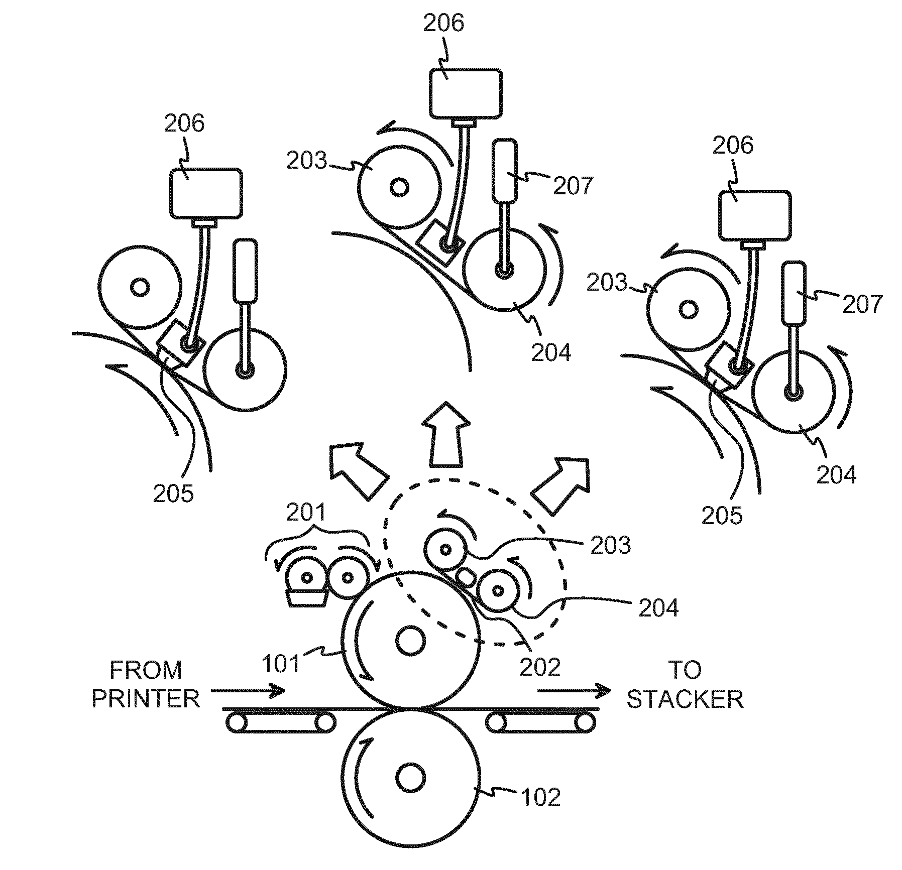
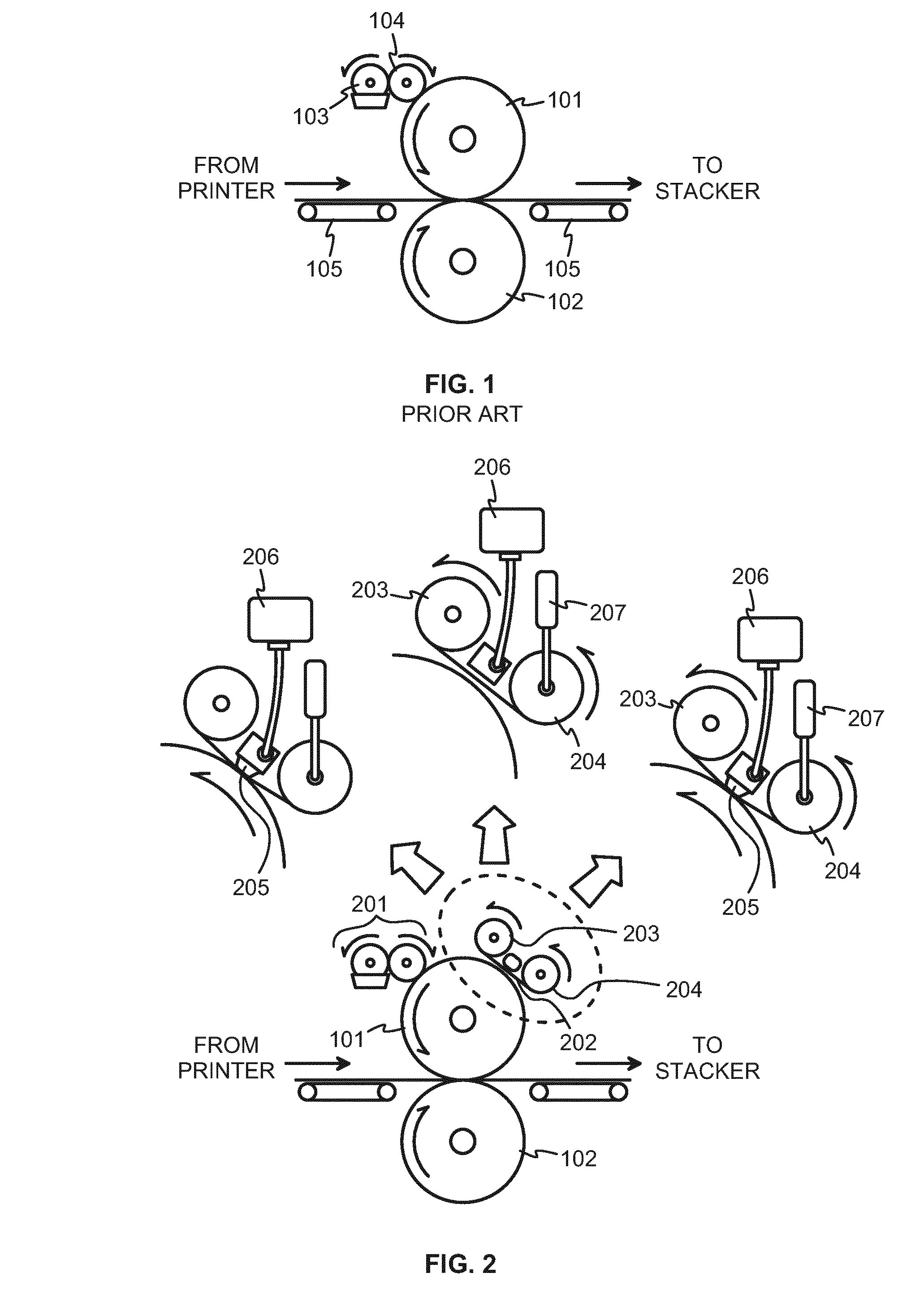
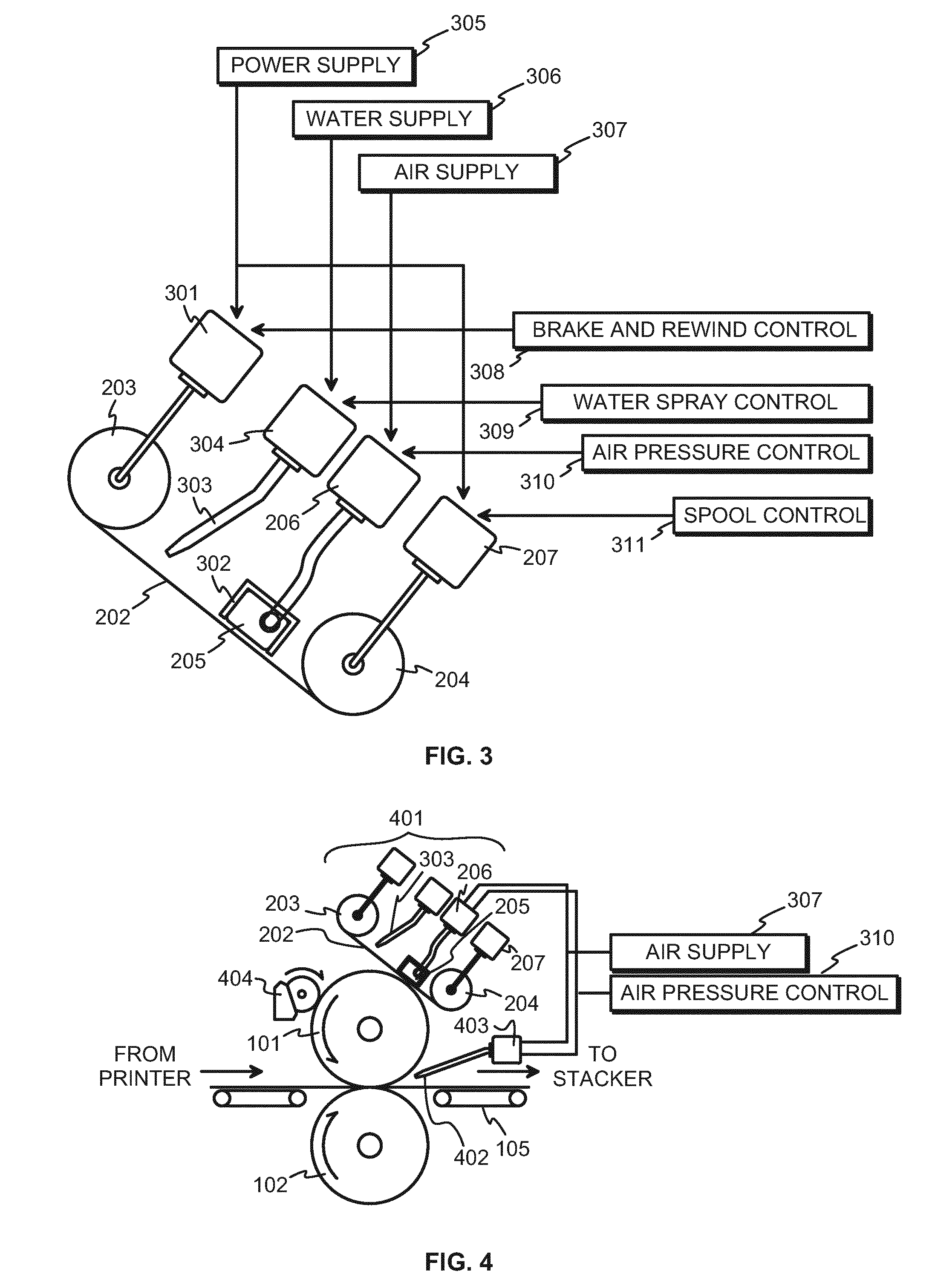
[0020]FIG. 2 illustrates schematically a coater, and especially a cleaning arrangement for a coater. The coater comprises a plate cylinder 101, which as a general description means a rotatable cylindrical body, the outer surface of which is meant to press against a workpiece in the purpose of transferring coating substance, which has been previously spread on said outer surface, onto desired portions of the surface of the workpiece. Means for spreading the coating substance on the outer surface of the plate cylinder are schematically shown at 201 in FIG. 2, and they can comprise a fountain roller and an anilox roller or they may be implemented otherwise, for example, with only an anilox roller without a separate fountain roller. The way in which the coating substance is spread on the outer surface of the plate cylinder 101 is not important to the present invention. An impression cylinder 102 is also shown in FIG. 2. Together with the plate cylinder 101, the impression cylinder or a ...


PUM


Abstract

A cleaning arrangement for a coater that has a plate cylinder, the cleaning arrangement having a cleaning web, a tangential moving mechanism configured to controllably move the cleaning web in at least one direction in a plane defined by the cleaning web, a radial moving mechanism configured to controllably move the cleaning web in at least one direction out of the plane, and a controller coupled to the tangential and radial moving mechanisms which is configured to control the moving of the cleaning web into and out of contact with the plate cylinder in conformity with input signals received by the controller.

Description

BACKGROUND OF THE INVENTION[0001]1. Field of the Invention[0002]The invention concerns, in general, the technology of automatic maintenance operations in printing and package manufacturing machinery. Especially the invention concerns the task of maintaining smooth and reliable operation of a coater that on a manufacturing line comes after a sheet-fed printer.[0003]2. Description of Related Art[0004]Many manufacturing processes involve handling workpieces initially in planar, sheet-like form. As an example, the manufacturing process of packages is considered. The manufacturing process is typically arranged so that it takes advantage of the relatively easy handling of workpieces at the stage when they are still in planar form. A typical process for manufacturing cardboard packages comprises at least a printer, a stacker, and a die cutter in this order. Coaters, dryers, and / or other arrangements may follow the printer for implementing steps that, from the viewpoint of printing, represe...

Claims


Application Information

Patent Timeline
IPC IPC(8): B41F35/02B05C11/00B05C1/00
CPCB41F35/02B05C11/00B05C1/00B41F33/16B41F35/00B41F23/08B41P2235/242B41P2235/244B41P2235/246B41P2235/26B41F19/001
Inventor KYLLING, MADSRYYNANEN, MARKOGYDESEN, ERIKSIRVIO, PETRI
Owner TRESU
Learn More