
Hotwire deposition material processing system and method

a technology of material processing and hot wire, applied in the field of welding, can solve the problems of inability to maintain the desired temperature of the electrode wire, insufficient traditional control methods,

Active Publication Date: 2015-03-26
ILLINOIS TOOL WORKS INC
View PDF9 Cites 35 Cited by
  • Summary
  • Abstract
  • Description
  • Claims
  • Application Information

AI Technical Summary

Benefits of technology

The present patent relates to methods and systems for material processing. The technical effects include regulating the temperature of the material processing tool (electrode) to improve the quality of the material processing operation. This can be achieved by regulating the enthalpy of the electrode end using either current or power supply. A material processing system includes a power supply, a wire electrode feeder, and a control system for regulating enthalpy. This allows for better control and quality of material processing.

Problems solved by technology

While very effective in many applications, traditional control methodologies are generally inadequate for hotwire processes.
For example, traditional regulation schemes (“constant current” or “CC”, and “constant voltage” or “CV”) cannot maintain a desired electrode wire temperature because the control feedback variable does not necessarily correlate directly to enthalpy.

Method used


Image

  • Hotwire deposition material processing system and method
  • Hotwire deposition material processing system and method
  • Hotwire deposition material processing system and method

Examples


Embodiment Construction

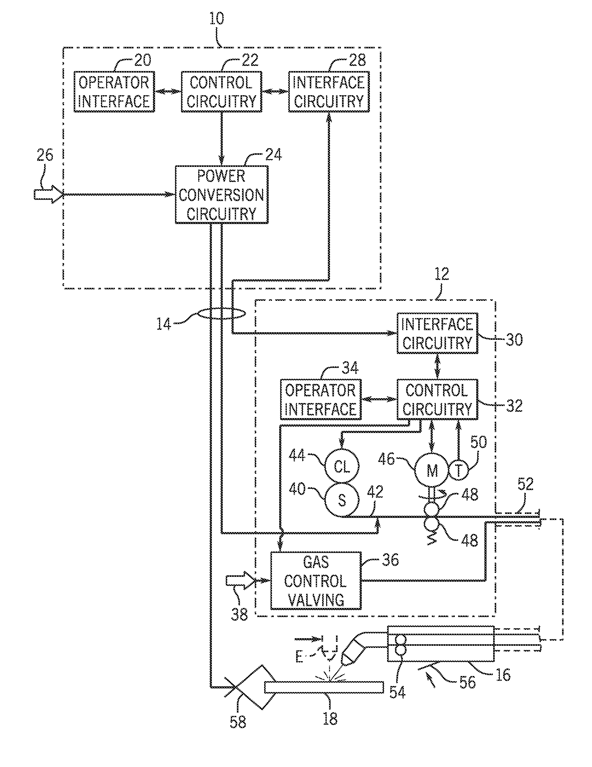
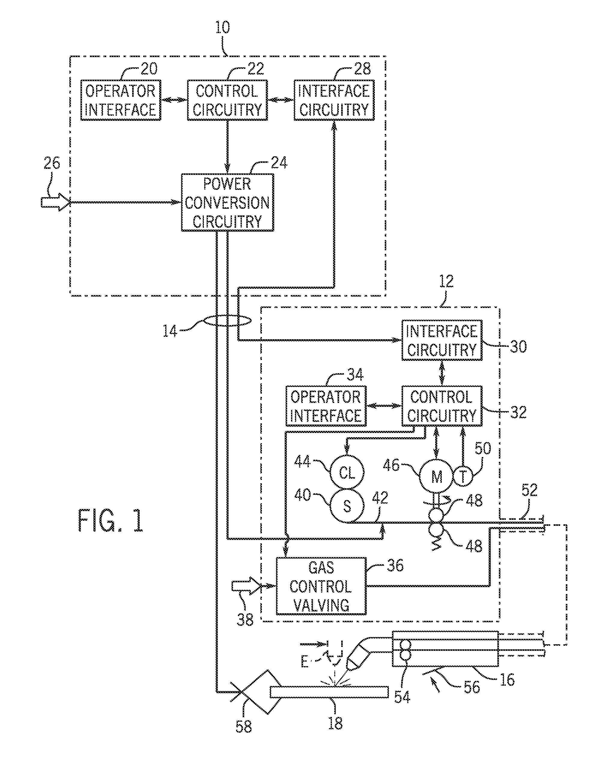
[0016]Turning now to the drawings, and referring first to FIG. 1, an exemplary material processing system is illustrated as including a power supply 10 and a wire feeder 12 coupled to one another via conductors or conduits 14. In the illustrated embodiment the power supply 10 is separate from the wire feeder 12, such that the wire feeder may be positioned at some distance from the power supply near a material processing location. However, it should be understood that the wire feeder, in some implementations, may be integral with the power supply. In such cases, the conduits 14 would be internal to the system. In embodiments in which the wire feeder is separate from the power supply, terminals are typically provided on the power supply and on the wire feeder to allow the conductors or conduits to be coupled to the systems so as to allow for power and gas to be provided to the wire feeder from the power supply, and to allow data to be exchanged between the two devices.

[0017]The system...


PUM

PropertyMeasurementUnit
Temperatureaaaaaaaaaa
Diameteraaaaaaaaaa
Densityaaaaaaaaaa

Abstract

A material processing system includes a power supply and a wire feeder to feed a wire electrode for a material processing operation. The enthalpy and / or temperature of a region of the tip of the electrode is maintained substantially constant via closed loop control. The control may be based upon regulation of current applied to the electrode. The control of the current may be based upon an electrode extension error. Wire feed speed may also be controlled to assist in maintaining a substantially constant enthalpy and / or temperature near the electrode tip.

Description

BACKGROUND[0001]The invention relates generally to welders, and more particularly to a welder configured to perform a preheating operation on an electrode material prior to execution of a material processing operation.[0002]A wide range of material processing systems and material processing control regimes have been implemented for various purposes. In continuous material processing operations, gas metal arc material processing (GMAW) techniques, and a particular class referred to as metal inert gas (MIG) techniques allow for formation of a continuing weld bead by feeding material processing wire shielded by inert gas from a material processing torch. Electrical power is applied to the material processing wire and a circuit is completed through the workpiece to sustain an arc that melts the wire and the workpiece to form the desired weld. In related techniques, a flux cored wire may be used without a shielding gas.[0003]Advanced forms of MIG material processing are based upon genera...

Claims


Application Information

Patent Timeline
IPC IPC(8): B23K28/00B23K9/10B23K9/04
CPCB23K28/00B23K9/1006B23K9/04B23K9/095B23K9/0953B23K9/124B23K9/125B23K9/28
Inventor SCOTT, KEVIN MICHAELHUTCHISON, RICHARD MARTIN
Owner ILLINOIS TOOL WORKS INC
Features
  • Generate Ideas
  • Intellectual Property
  • Life Sciences
  • Materials
  • Tech Scout
  • Unparalleled Data Quality
  • Higher Quality Content
  • 60% Fewer Hallucinations
Learn More