Method for determining the spatial distribution of magnetic resonance signals in subvolumes of an object under examination

Active Publication Date: 2015-03-26
BRUKER BIOSPIN MRI
View PDF3 Cites 8 Cited by
  • Summary
  • Abstract
  • Description
  • Claims
  • Application Information

AI Technical Summary

Benefits of technology

[0013]MRI and MRS methods are also known in which nuclear spins within one or more spatially separated areas under examination, and only there, are simultaneously excited selectively by means of multidimensional RF excitation and, during this excitation, a phase encoding is superposed onto the magnetic resonance signals by means of a suitable encoding scheme, which if the magnetic resonance signals of all areas under examination are acquired simultaneously, permits separation of the signals according to the area they originate from and/or determination of their spatial distribution within these areas [4].
[0014]According to the method disclosed in [5], it is also possible to create phase patterns of transverse magnetization during excitation in order to achieve partial or full spatial encoding of the magnetic resonance signals during excitation. By repeating excitation with different phase patterns as defined by a phase encoding scheme, an entire data set is collected in multiple phase encoding steps, which is then reconstructed spatially resolved according to the spatial encoding scheme and which provides, for example, two- or three-dimensional images of the object under examination. This method of spatial encoding will hereinafter be referred to as excitation encoding. Analogously, this method of spatial encoding with RF transmission phases can also be applied with spatially selective inversion or refocusing. Generally, the term transmission encoding will be used from now on when spatial encoding of the magnetization is generally applied during irradiation of spatially selective RF pulses.
[0015]For the practical use of mufti-dimensional RF pulses, a further aspect of technical progress of the past few has years has proven advantageous, which is described in detail in [6]. In the past, the spatially selective excitation was initially performed using a single RF transmission antenna with an essentially homogeneous transmission field (B1 field) in conjunction with the gradient system. Inspired by the success of parallel imaging, in which signal acquisition is performed with RF reception antenna equipment with multiple reception elements, also termed antenna array in the specialist literature, it has now become customary to also use such RF transmission antenna devices, which consist of multiple transmission elements operated on multiple, independent RF transmission channels of the MR apparatus, for transmission in spatially selective excitation. In this way, it is possible to partially replace the spatial encoding, which in the case of multi-dimensional RF pulses by analogy with data acquisition is implemented by varying additional magnetic fields, with so-called sensitivity encoding and thus to reduce the length of the

Problems solved by technology

One of the basic issues when using spatially selective excitation is determination of the RF pulses to be replayed by the transmission antenna device to generate the desired excitation pattern in conjunction with additional magnetic fields, e.g. by describing a k-space trajectory.
Otherwise, non-spatially encoded signal components would cause image artifacts and other worsening of mapping accuracy and image quality.
A disadvantage of this inventive method is initially the necessity to prevent, as far as possible, any MR signals from being generated outside the RoI(s) during RF excitation, since any residual signal could contribute to falsifying the image.
This necessity makes th

Method used


Image

  • Method for determining the spatial distribution of magnetic resonance signals in subvolumes of an object under examination
  • Method for determining the spatial distribution of magnetic resonance signals in subvolumes of an object under examination
  • Method for determining the spatial distribution of magnetic resonance signals in subvolumes of an object under examination

Examples


Embodiment Construction

[0042]Further variants and further advantageous characteristics and embodiments are described in the dependent claims.

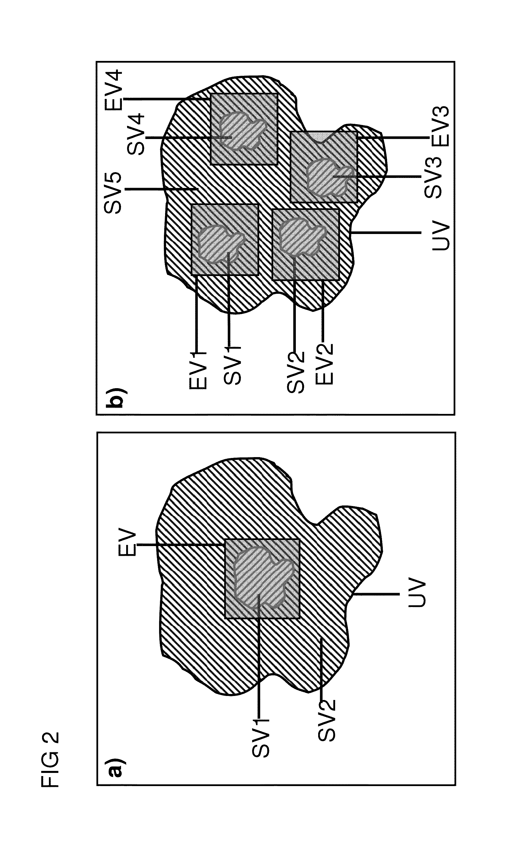
[0043]In a variant of the inventive method, the transmission encoding scheme only defines the spatially dependently amplitude of the transverse magnetization to be set by means of the magnetization change across the I transmission encoding steps. Encoding according to the transmission encoding scheme therefore comprises amplitude encoding by varying the amplitudes of transverse magnetization across the I encoding steps. One possible variant for such an amplitude encoding for N subvolumes would be to set an amplitude A1 of transverse magnetization in a different subvolume in each encoding step of the transmission coding scheme and to set an amplitude A2 that differs from A1 in the remaining subvolumes.

[0044]An alternate variant is especially preferred, in which the transmission encoding scheme only defines the phase of the transverse magnetization to be set spatially ...


PUM


Abstract

A method for determining the spatial distribution of magnetic resonance signals from at least one of N subvolumes predefines a reception encoding scheme and determines unique spatial encoding for at least one of the subvolumes but not for the entire volume under examination (UV). A transmission encoding scheme is also defined, wherein encoding is effected via the amplitude and/or phase of the transverse magnetization. The temporal amplitude and phase profile of the RF pulses is then calculated and each reception encoding step is carried out I times with variations according to the I transmission encoding steps in the transmission encoding scheme. The method makes it possible to largely restrict the spatially resolving MR signal encoding and image reconstruction to subvolumes of the object under examination without the achievable image quality sensitively depending on imperfections in the MR apparatus.

Description

[0001]The invention relates to a method for determining the spatial distribution of magnetic resonance signals from one or more non-overlapping subvolumes of an object under examination in the measurement volume of a magnetic resonance apparatus.[0002]Such a method is known from [1].[0003]In the method known from [1], a reception encoding scheme for spatial encoding of the magnetic resonance signals is used to reduce the measurement duration and / or to improve the spatial resolution, which defines unique spatial encoding in at least one dimension only for limited partial regions of the object under examination. The necessary uniqueness of spatial allocation of the received magnetic resonance signals is achieved by irradiating spatially selective radio-frequency pulses during execution of each spatial encoding step of the reception encoding scheme to excite transverse magnetization, which limit transverse magnetization contributing to subsequent signal acquisition within the object un...

Claims


Application Information

Patent Timeline
IPC IPC(8): G01R33/483G01R33/24G01R33/385G01R33/561
CPCG01R33/4833G01R33/385G01R33/246G01R33/561A61B5/055G01R33/4836G01R33/5612
Inventor RUHM, WOFGANGSCHNEIDER, JOHANNESULLMANN, PETER
Owner BRUKER BIOSPIN MRI
Why Eureka
Try Eureka