
Arrangement for separation of particles, and a separation method in connection with a process for manufacturing power cables

Inactive Publication Date: 2006-02-02
SVANTE BJOERK
View PDF9 Cites 1 Cited by
  • Summary
  • Abstract
  • Description
  • Claims
  • Application Information

AI Technical Summary

Benefits of technology

[0014] The aim of the present invention is to provide an improved arrangement for separating unwanted loose particles, for example in connection with the inspection and sorting of granules.
[0016] Another aim of the invention is to provide an improved method in connection with the manufacture of electrical power cables, in which unwanted particles that can potentially weaken the insulation can be separated before an insulating covering is manufactured for the said power cables.
[0018] Another aim of the invention is to provide an improved arrangement for inspecting principally granular elements that are fed towards an inspection station comprising an optical detector, which arrangement permits the separating of unwanted loose particles before or after the said inspection station.

Problems solved by technology

Concerning electrical power cables, it is of the greatest importance that there are no contaminants in the insulating polyethylene covering, as such contaminants can lead to a limited life for the cable as a result of breakdown of the insulation material, which in turn leads to electrical puncture of insulation in the cable.
Such puncture results in turn in the cable being damaged.
In this way, the granules that have some form of defect (for example in the form of air bubbles, contaminants, variations in symmetry, variations in colour, etc.) are separated and discarded, as they could otherwise cause the abovementioned problems in the finished cable.
This makes the detection of the particles more difficult, as they can lie under the flow of granules which are to be inspected.
This means that there is a risk that they are not discovered and separated during the abovementioned type of optical detection.

Method used


Image

  • Arrangement for separation of particles, and a separation method in connection with a process for manufacturing power cables
  • Arrangement for separation of particles, and a separation method in connection with a process for manufacturing power cables
  • Arrangement for separation of particles, and a separation method in connection with a process for manufacturing power cables

Examples


Embodiment Construction

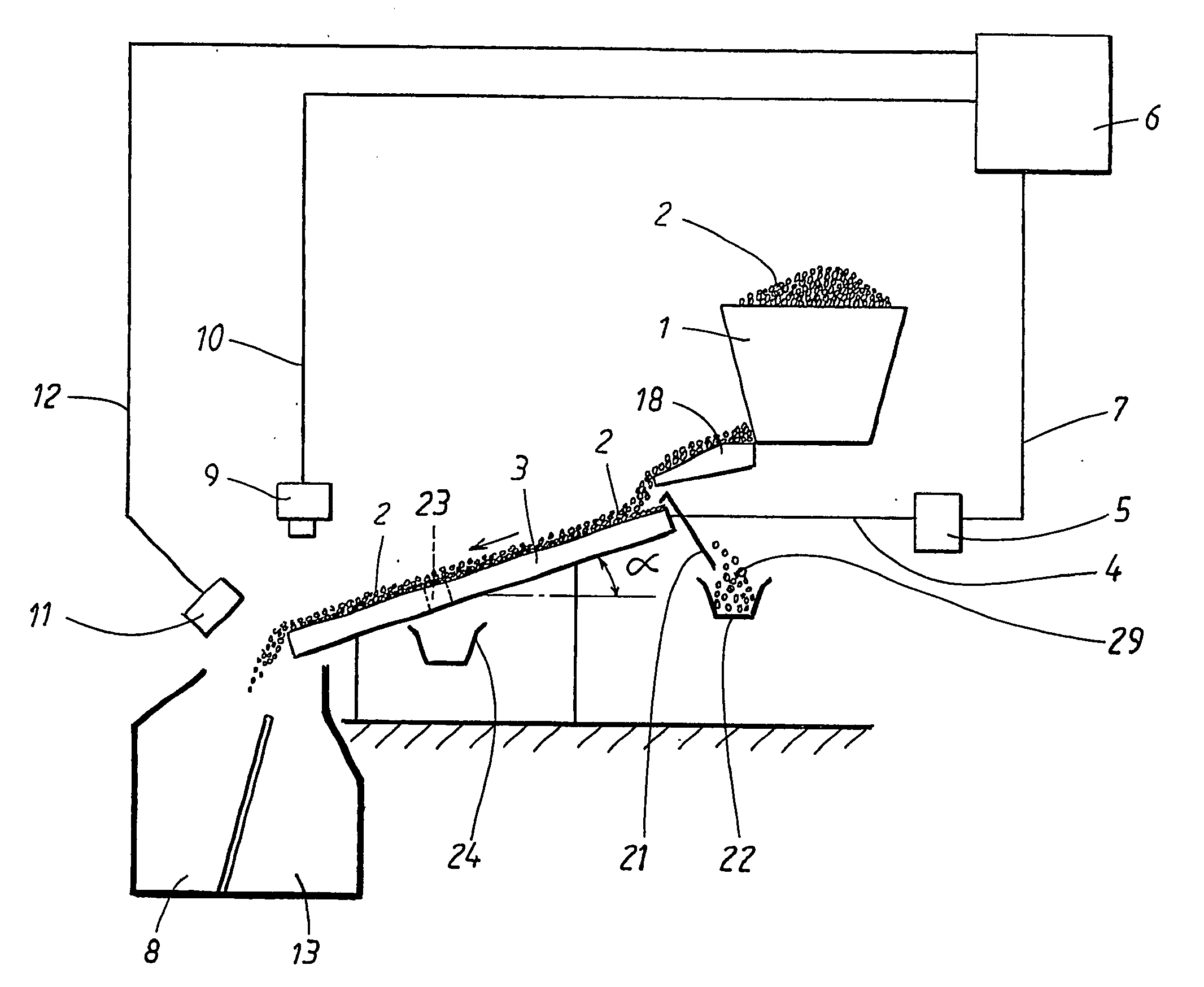
[0026]FIG. 1 shows a schematic and somewhat simplified side view of a sorting and detecting system in which the present invention can be used. According to a preferred embodiment, the system comprises a feeding arrangement, preferably in the form of a hopper 1 for a certain quantity of granules 2, that is to say elements principally in the shape of small balls or grains. The invention is particularly suitable for use in connection with a system for inspecting granules 2 of material which in turn is used for manufacturing electrical power cables for high and medium-high voltages (from approximately 12 kV and upwards), with the granules 2 constituting a raw material of polyethylene that is used for manufacturing an electrically insulating covering in such power cables.

[0027] The invention is not limited to the use of only such materials as mentioned above. Nor is the invention limited to being used with inspection and detection systems for such materials, but can be used for any form...


PUM


Abstract

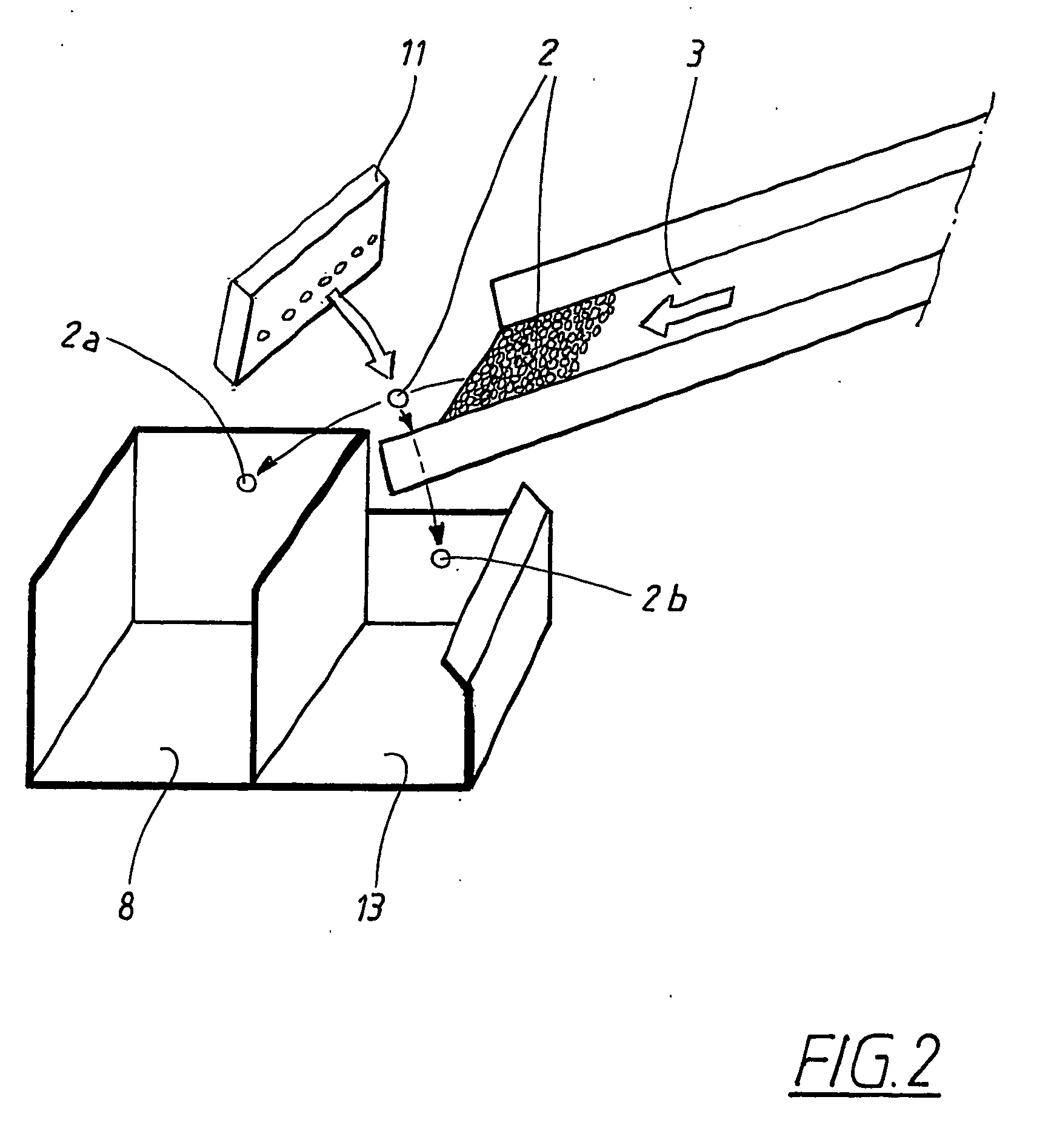
The invention relates to an arrangement for separating particles from a flow of pellet-shaped or granular elements that are fed from a source to a subsequent workstation for processing the said elements. The invention is characterized in that the said arrangement comprises a screen arrangement that is arranged downstream of the said source and that comprises a plurality of projections extending in principally the same direction as the direction of feed for the said elements and with principally V-shaped spaces between the said projections, which spaces increase gradually in the direction of flow, whereby particles of a size that is smaller than the size of the said elements are separated from the said flow of elements by falling down through the said spaces. The invention also relates to a method for manufacturing electrical power cables, and an arrangement for inspecting elements.

Description

BACKGROUND OF THE INVENTION [0001] 1. Field of Invention [0002] The present invention relates to an arrangement for separation of particles, as claimed in the preamble to claim 1. [0003] In particular, the invention is intended to be used in connection with the separation of particles in connection with optical inspection, checking and cleaning of granules of synthetic material, which in turn are used for the manufacture of electrical power cables. [0004] The invention also relates to a separation method in connection with a process for manufacturing electrical power cables, as claimed in the preamble to the following claim 13. [0005] The invention also relates to an arrangement for inspection of elements, as claimed in the preamble to the following claim 16. [0006] 2. Discussion of Prior Art [0007] In the manufacture of electrical power cables for high and medium-high voltages, preferably of the order of 12 kV and higher, an electrical conductor is normally provided with a semi-con...

Claims


Application Information

Patent Timeline
IPC IPC(8): B07B13/07B07C5/342
CPCB07B13/07B07C5/368B07C5/3425
Inventor BJORK, SVANTE
Owner SVANTE BJOERK
Learn More