Cable clamp and harness

a technology of cable clamping and harness, which is applied in the direction of insulated conductors, cables, coupling device connections, etc., can solve the problems of increasing mechanical load on the electric wire section of the electric cable, and achieve the effect of enhancing the gripping force of the cabl

Active Publication Date: 2015-04-02
HITACHI METALS LTD
View PDF7 Cites 4 Cited by
  • Summary
  • Abstract
  • Description
  • Claims
  • Application Information

AI Technical Summary

Benefits of technology

[0008]Now, when as described above, the electric cable is inserted into the cylindrical portion of the cable clamp and the cylindrical portion is swaged, the larger amount of deformation of the cylindrical portion results from the swaging, the stronger electric cable gripping force (herein also simply referred to as “gripping force” or “cable gripping force”) the cylindrical portion has. For this reason, when the electric cable is desired to be fixed with a stronger gripping force for the purpose of, for example, enhancing reliability when used for automobiles, it is necessary to increase a swaging load. The swaging load refers to a load applied to the cylindrical portion when the cylindrical portion is swaged using a swaging tool.
[0018](iii) The second cylindrical portion includes a deformation relieving portion around a flange side thereof relative to a swaged portion thereof, to relieve deformation of the flange due to the swaging.
[0025]The invention allows for, when the electric cable is fixed by swaging using the cable clamp, being able to enhance cable gripping force without increasing a load acting on the electric wire section of the electric cable.

Problems solved by technology

However, increasing the swaging load when swaging the cylindrical portion of the cable clamp leads to an increase in mechanical load acting on the electric wire section of the electric cable.

Method used


Image

  • Cable clamp and harness
  • Cable clamp and harness
  • Cable clamp and harness

Examples


Embodiment Construction

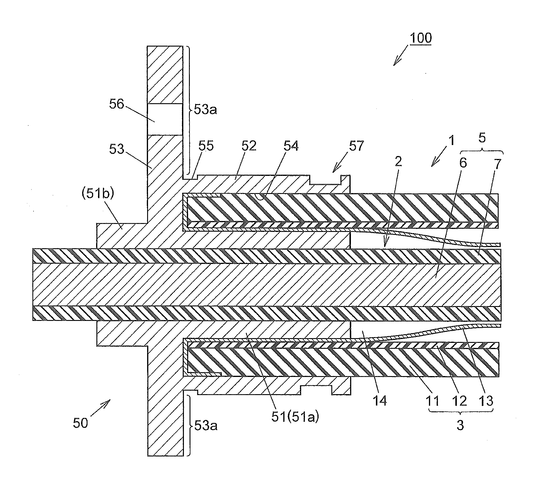
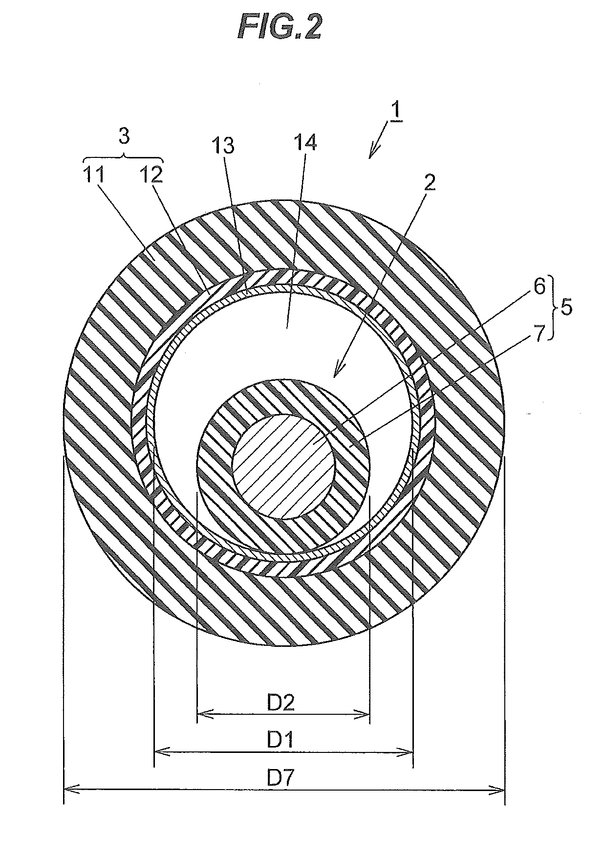
[0035]Below is described an embodiment according to the invention in detail, in conjunction with the accompanying drawings. In the embodiment according to the invention, the following descriptions are in turn given:

1. Harness outline

2. Electric cable configuration

3. Technical significance of providing a reinforcing braid layer

4. Relationship between an electric wire section and a protecting section

5. Cable clamp configuration

6. Harness configuration

7. Harness attachment

8. Functions and advantageous effects of the embodiment

9. Modifications

1. Harness Outline

[0036]FIG. 1 is a cross sectional view showing a configuration example of an essential portion of a harness 100 in an embodiment according to the invention. The harness 100 illustrated is configured to include an electric cable 1 and a cable clamp 50. Below are described, in turn, respective configurations of the electric cable 1 and the cable clamp 50, followed by a configuration of the harness 100 with the electric cable 1 and t...


PUM

PropertyMeasurementUnit
thicknessaaaaaaaaaa
diameteraaaaaaaaaa
diameteraaaaaaaaaa

Abstract

A cable clamp is configured to fix an electric cable including an electric wire section and an outer layer section covering the electric wire section to a fixed member. The cable clamp includes a first cylindrical portion for the electric wire section to be inserted therein, and a second cylindrical portion formed around outside the first cylindrical portion to surround the first cylindrical portion. The second cylindrical portion includes a receiving portion formed between it and the first cylindrical portion to receive the outer layer section. The second cylindrical portion is swaged with the electric wire section inserted in the first cylindrical portion and with the outer layer section received in the receiving portion, so that the outer layer section is gripped by the first cylindrical portion and the second cylindrical portion.

Description

[0001]The present application is based on Japanese patent application No. 2013-203725 filed on Sep. 30, 2013, the entire contents of which are incorporated herein by reference.BACKGROUND OF THE INVENTION[0002]1. Field of the Invention[0003]This invention relates to a cable clamp to be used for fixing an electric cable, and a harness using the same.[0004]2. Description of the Related Art[0005]In recent years, due to widespread use of robots, electrical equipment for automobiles, etc., electric cables have been used even in environments where they undergo repeated bendings. It is known that the electric cables of this type have a structure in which an electric wire section is configured by use of one or more electric wires and is protected with a sheath therearound.[0006]Also, a known method to fix the electric cable is to use a cable clamp. Specifically, that known method fixes the electric cable by integrally forming a cylindrical portion on the cable clamp, inserting the electric c...

Claims


Application Information

Patent Timeline
Patent Type & Authority Applications(United States)
IPC IPC(8): H01R4/28H01B7/00
CPCH01B7/0045H01R4/28H02G3/0481H02G3/0616H02G3/22
Inventor ESHIMA, HIROTAKAOKA, FUMIHITOYAMASHITA, NOBUYUKIFUTATSUMORI, TAKAHIRO
Owner HITACHI METALS LTD
Why Eureka
Try Eureka