Power supply device, and vehicle and storage battery device equipped with power supply device

Inactive Publication Date: 2015-04-02
SANYO ELECTRIC CO LTD
View PDF3 Cites 21 Cited by
  • Summary
  • Abstract
  • Description
  • Claims
  • Application Information

AI Technical Summary

Benefits of technology

[0008]The present disclosure is developed for the purpose of solving such drawbacks. One non-limiting and explanatory embodiment provides a power supply device, a vehicle and a storage ba

Problems solved by technology

Further, in the battery cell, when it is quickly charged or discharged or at high temperature, rising in the internal pressure happens by the reason of some abnormality.
Then the gas from the safety valve leaks
In addition

Method used


Image

  • Power supply device, and vehicle and storage battery device equipped with power supply device
  • Power supply device, and vehicle and storage battery device equipped with power supply device
  • Power supply device, and vehicle and storage battery device equipped with power supply device

Examples


Example

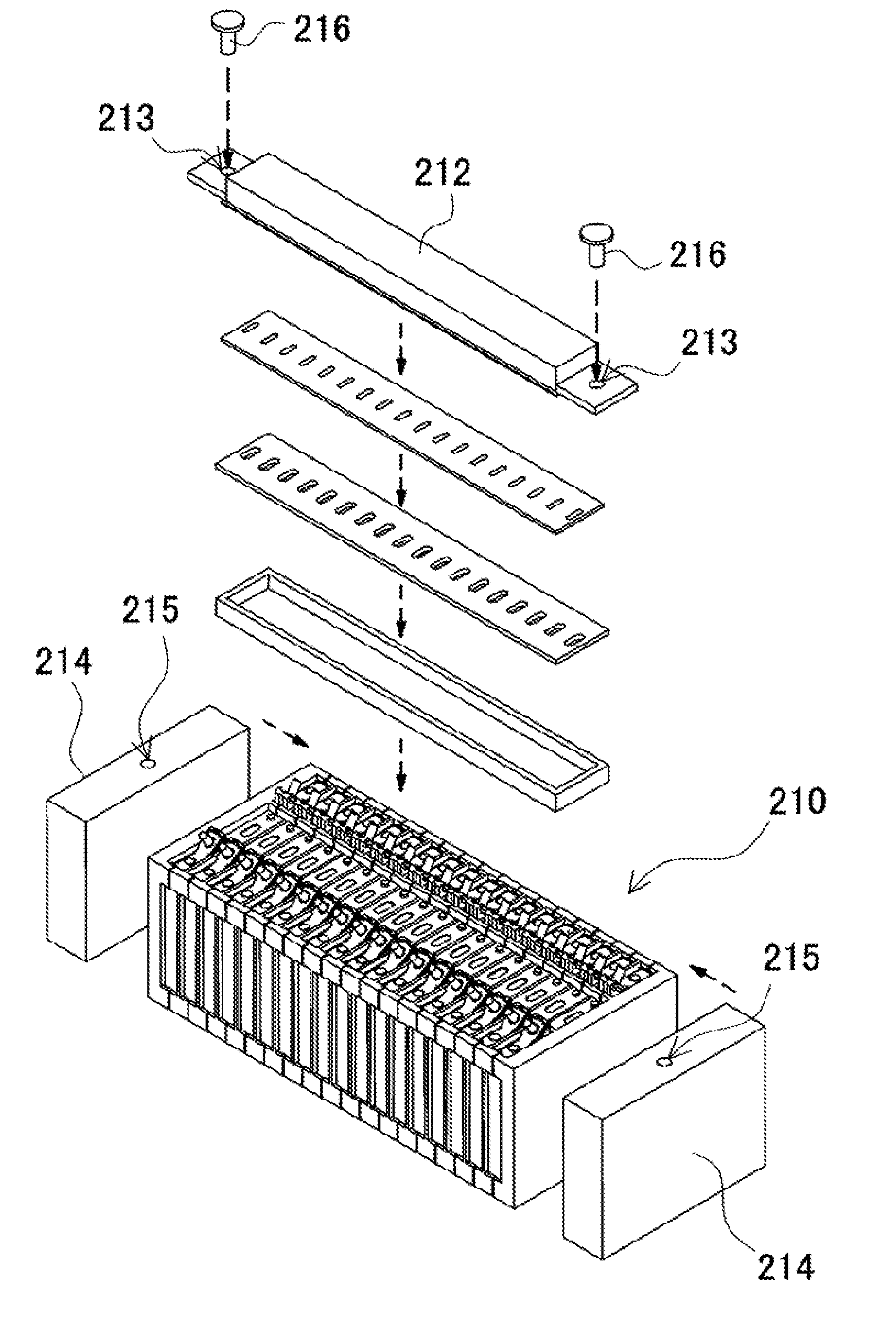
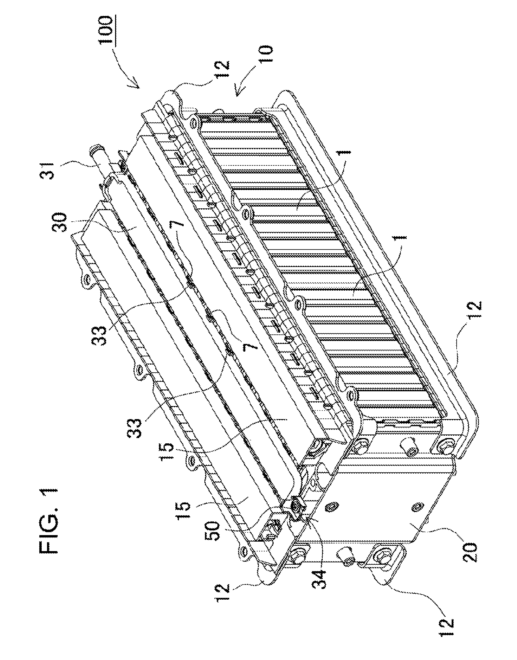
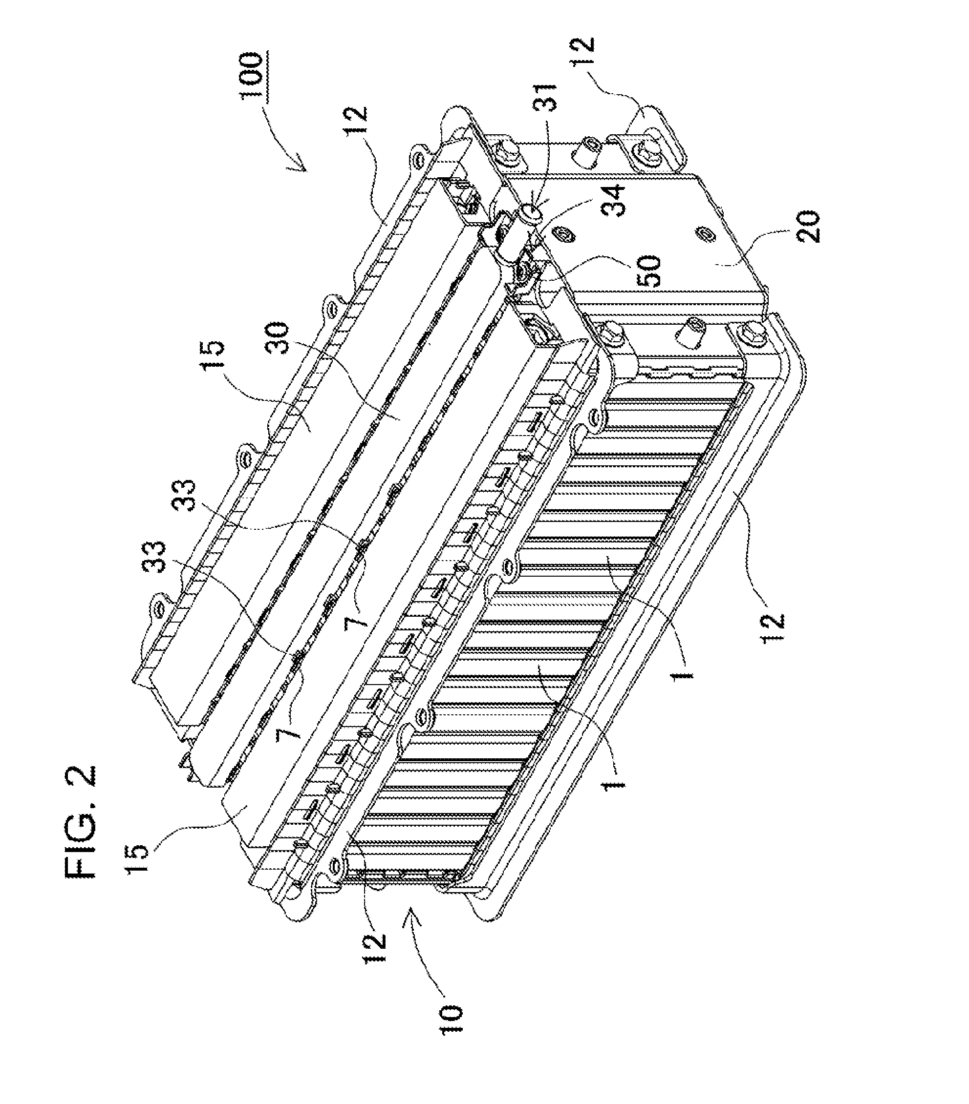
[0039]Hereinafter, the embodiment of the present invention will be described referring to drawings. However, the following embodiments illustrate a power supply unit, and a vehicle and a storage battery device equipped with this which is aimed at embodying the technological concept of the present invention, and the present invention is not limited to the power supply unit, and a vehicle and a storage battery device equipped with this described below. However, the members illustrated in Claims are not limited to the members in the embodiments. It is noted that the magnitude or positional relation of the members illustrated in each diagram is sometimes grandiloquently represented, in order to clarify the description. Furthermore, in the description below, identical names and reference numbers represent identical or homogeneous members, and detailed descriptions are appropriately omitted. Moreover, mode may be applied where each element constituting the present invention constitutes a ...


PUM


Abstract

A power supply device comprises a battery assembly formed by stacking secondary battery cells having safety valves for exhausting gas, end plates being arranged at both end faces of the battery assembly in the stacking direction, a gas duct guiding gas emitted from the safety valves in a prescribed gas exhaust passage, and fixing portions fixing both ends of the gas duct to the end plates in a position where the gas duct faces the safety valves. In a state in which the gas duct is fixed to the end plates in at least one of the fixing portion a fixing opening of a slit is formed extending in the direction parallel to the direction in which the secondary battery cells are stacked, and a fixing member is inserted into the slit fixing opening.

Description

TECHNICAL FIELD[0001]The present invention relates to a power supply device, a vehicle and a storage battery device equipped with the power supply device.BACKGROUND ART[0002]A power supply device having plural battery cells is used as a power source device installed in an electric vehicle such as a hybrid vehicle, an electric vehicle, or a home or industrial power storage. The battery cell used in such a power supply device has an exterior container made of metal. A battery assembly is formed by stacking the battery cells interposing a separator therebetween. And end plates are arranged at both end faces of the battery assembly, accordingly the battery assembly is sandwiched and fixed between the end plates.[0003]In order to exhaust gas at the time of rising in the internal pressure of the exterior container by a high temperature or the like, each battery cell has a safety valve. In order to emit and guide such gas safely, the safety valve and a duct are connected with consecutive s...

Claims


Application Information

Patent Timeline
IPC IPC(8): H01M2/12H01M50/209H01M50/264H01M50/293
CPCH01M2/1223H01M2220/20H01M2220/10H01M10/0481Y02E60/10H01M50/308H01M50/317H01M50/3425H01M50/209H01M50/293H01M50/264
Inventor KURIYAMA, TOMOHISAASAI, YASUHIROKOMAKI, TSUYOSHIFURUIE, YOSHIYAYANO, HIDEAKI
Owner SANYO ELECTRIC CO LTD
Why Eureka
Try Eureka