
Facade

a facade and cladding technology, applied in the field of cladding systems, can solve the problems of reducing thermal performance, reducing and little or no thermal insulation performance of cladding, and achieve the effect of increasing the resistance of cladding and being easy to install

Active Publication Date: 2015-04-09
JAMES HARDIE TECH LTD
View PDF29 Cites 43 Cited by
  • Summary
  • Abstract
  • Description
  • Claims
  • Application Information

AI Technical Summary

Benefits of technology

The present invention provides an easy-to-install, adjustable, concealed fix, façade system that allows for the façade panels to be mounted onto a structure using a panel support element. The façade panels form the exterior component of the façade system. The invention includes a channel formation on the panel retaining means, which allows for secure mounting of the façade panels onto the structure. The panel support element can have a biasing flange or a detent to improve fit and secure mounting of the façade panels. The technical effect of the invention is to provide a convenient and secure means of installing façade panels onto a structure.

Problems solved by technology

However, the clip or bracket system only provides point supports to the panel.
This can cause further difficulties in extreme weather conditions particularly when the façade panel is trimmed to fit specific wall dimensions.
Furthermore, whilst façade systems are effective when providing a weather tight exterior envelope they provide little or no thermal insulation performance.
These systems are more effective at providing thermal insulation performance, but, if the screed is breached, they lose their ability to provide a weather tight exterior envelope resulting in water ingress causing a reduction in thermal performance and possible damage to building structural elements.

Method used


Image

  • Facade
  • Facade
  • Facade

Examples


embodiment 500

[0094]In FIG. 5, there is shown a further embodiment 500 of the façade system of the invention. This embodiment of the invention differs from those of FIGS. 1 and 2 in that the retaining element 501 is connected to the structural building substrate 502 by means of an optional structural spacer element 520.

[0095]A structural support element 516 is installed into the structural building substrate 502. An optional spacer element 519 may then be placed over each structural support 516 before structural spacer elements 520 are mounted onto the structural support element 516. The optional spacer element 519 comprises, for example, a rubber or polymeric washer. The optional spacer element 519 functions to improve the ease of tightening of structural spacer element 516.

[0096]In the embodiment shown the structural support element 516 is integrally formed with the structural spacer element 520. Optionally, the structural support element 516 and structural spacer element 520 are preassembled t...

embodiment 800

[0107]FIG. 8 shows a cross-sectional view of a further embodiment 800 of a thermally efficient façade system of the invention. In this embodiment of the invention, panel retaining element 801 comprises a “T” section and channel 806 is formed between support plate 823 and panel retaining element 801. Panel retaining element 801 is fastened to support plate 823 by mechanical fastener 803. Support plate 823 is attached to structural spacer element 820 by means of the mutually engaging threaded portion 825. As before the structural spacer element 820 is secured to the structural support element 816 by mutually engaging threaded portions 521. The structural support element 816 is secured in position by means of a supporting bracket 817 which is secured in position by securing means 818. Insulating material 815 is disposed between the supporting bracket 817 and the supporting plate 823. Building wrap 822 is provided on the face of the insulating material 815 remote from the building subst...


PUM


Abstract

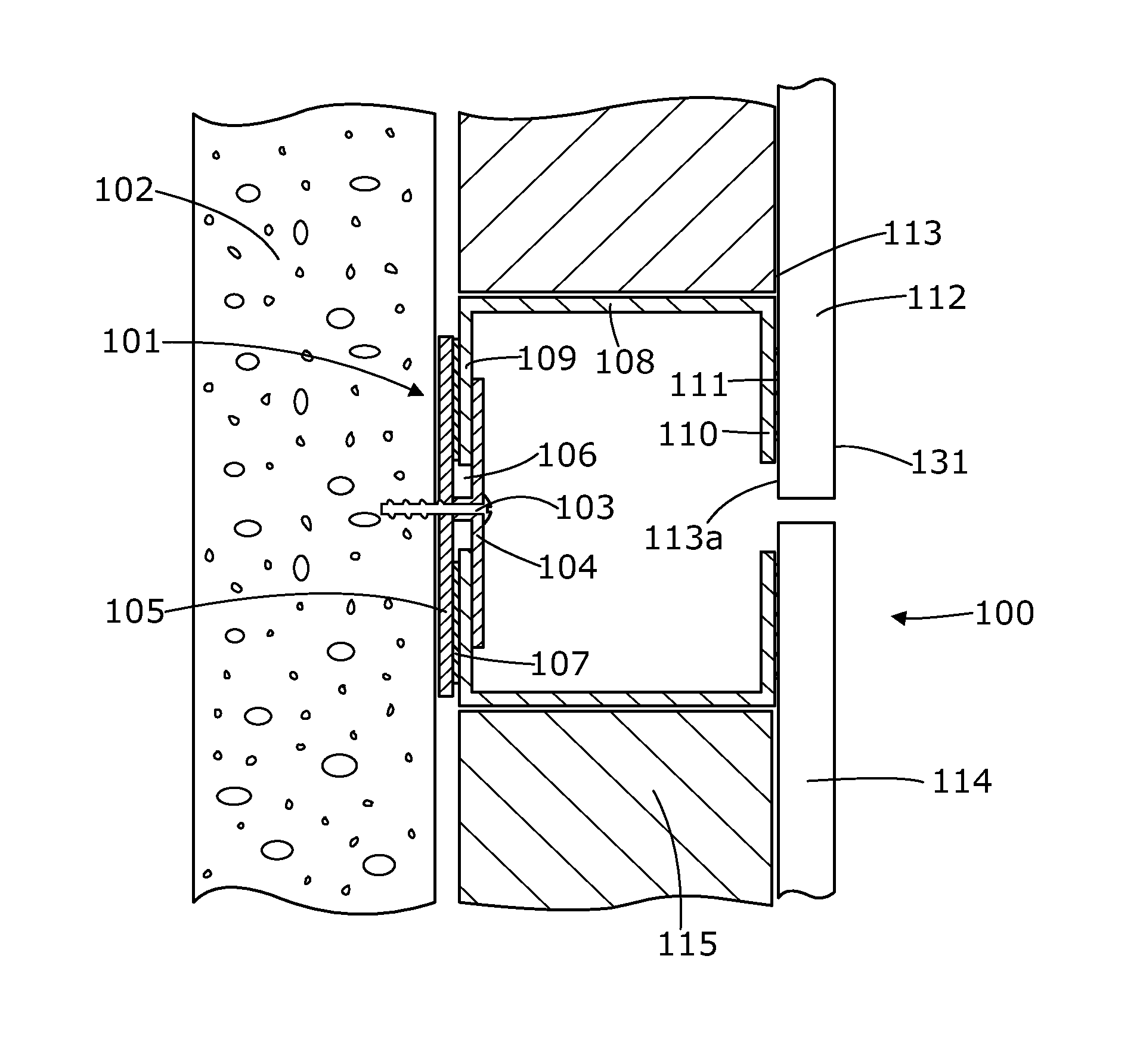
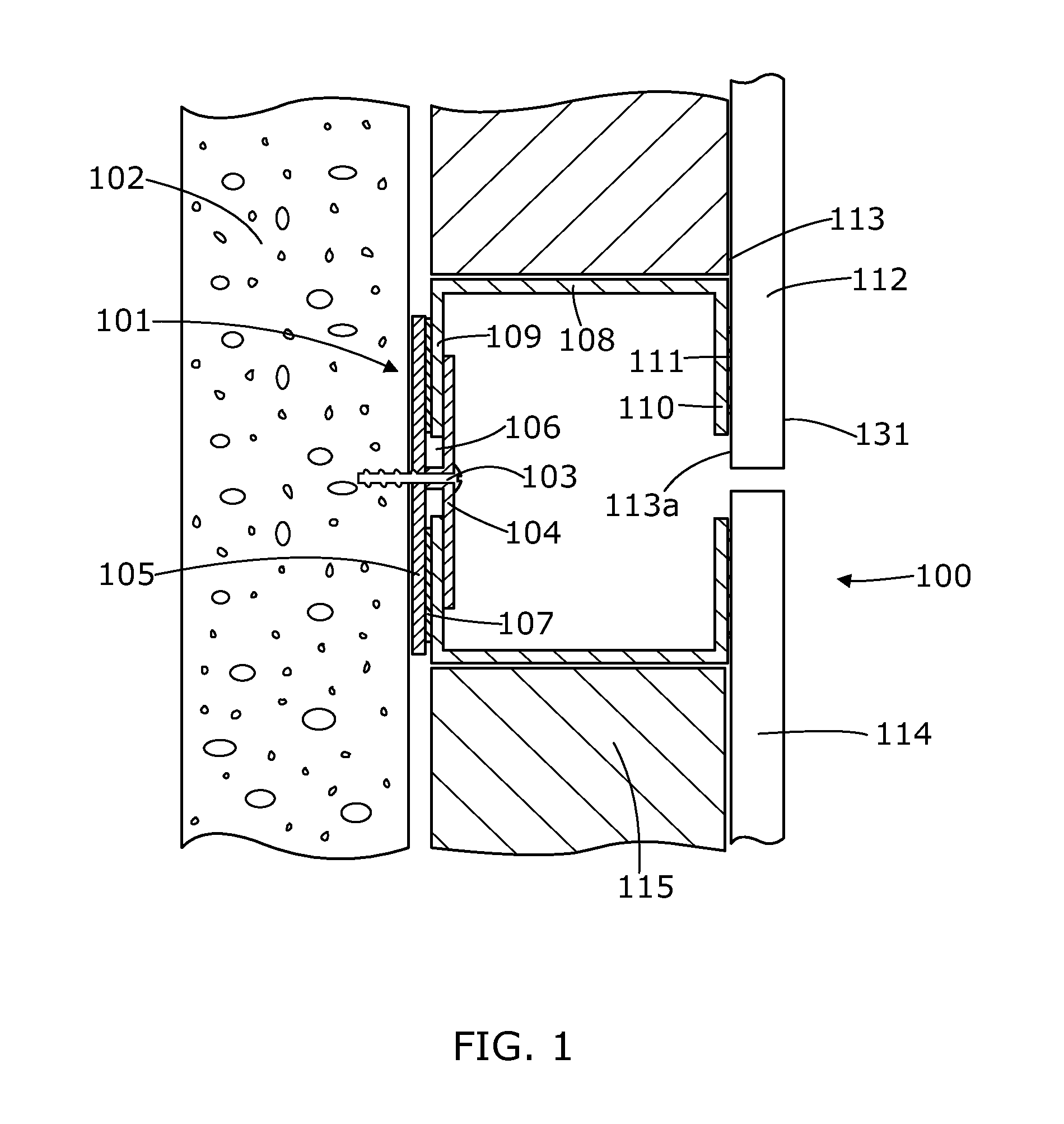
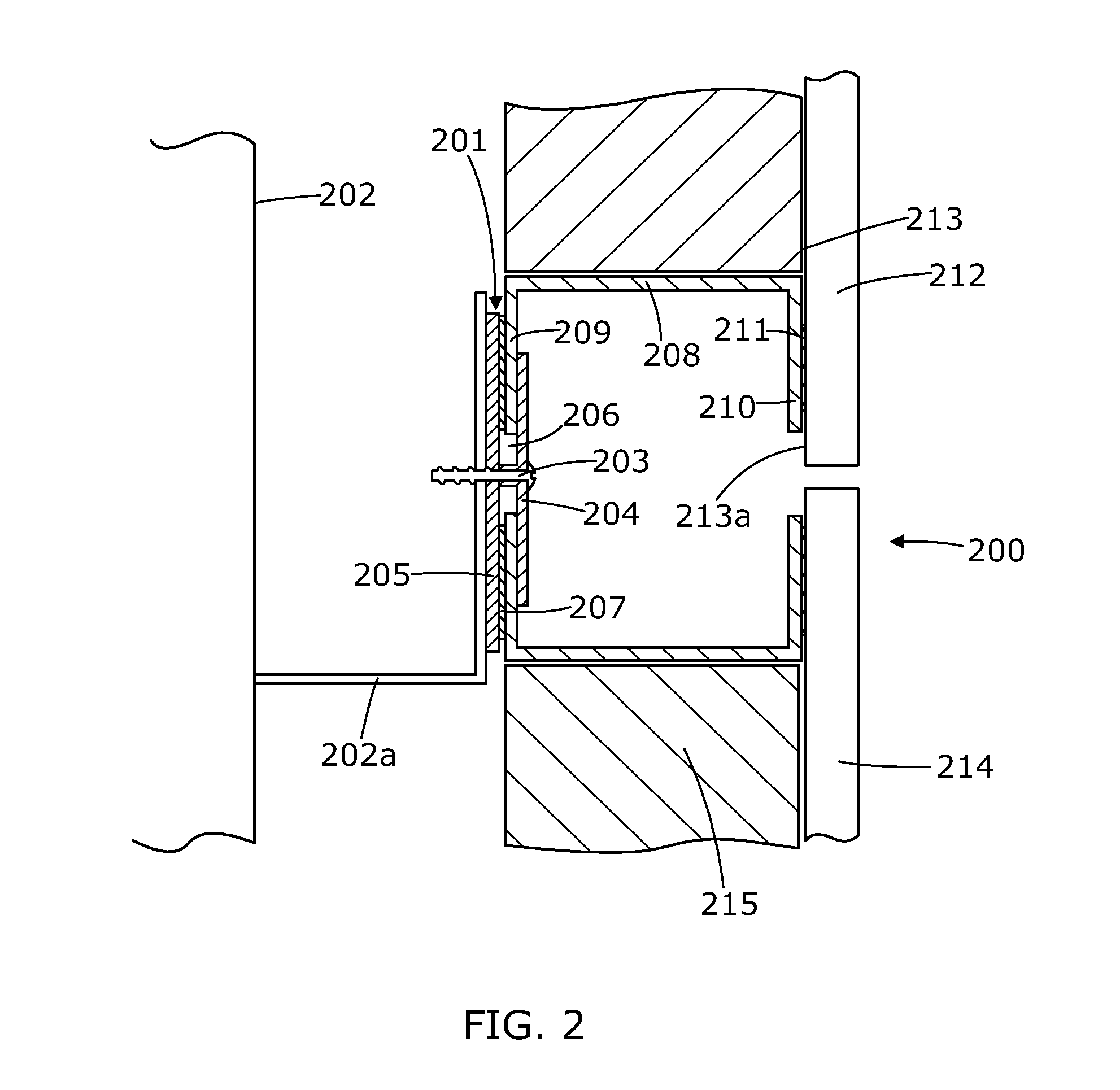
A façade (100) comprising at least one façade panel (112) having a front face (131) and a rear face (113) and at least two panel support elements (108). Each panel support element (108) comprises a first arm (110), a second arm (109) wherein at least a portion of the second arm (109) is attached to the rear face (113) of the façade panel (112). The panel support element (108) also comprising at least two panel retaining elements (101), each comprising a first flange (104) and a channel 106, wherein at least a portion of the second arm (109) of the panel support element (108) is restrained within the channel (106) and each panel retaining element (101) is attached to a building structural substrate (102).

Description

FIELD OF THE INVENTION[0001]The present invention relates to a façade system and in particular to an exterior façade system suitable for use in building construction.[0002]The invention has been developed primarily for use as an exterior façade cladding system suitable for use in building construction and will be described hereinafter with reference to this application. However, it will be appreciated that the invention is not limited to this particular field of use.BACKGROUND OF THE INVENTION[0003]Any discussion of the prior art throughout the specification should in no way be considered as an admission that such prior art is widely known or forms part of the common general knowledge in the field.[0004]Façade systems for new buildings are widely known. Façade panels of various types of materials, including coated aluminium and polymer composite materials are fixed to a structural frame, generally a metal frame, to provide a weather tight exterior envelope on a building. Such panels...

Claims


Application Information

Patent Timeline
Patent Type & Authority Applications(United States)
IPC IPC(8): E04F13/00E04F13/14E04F13/23E04F13/25E04B1/41E04B1/62
CPCE04F13/007E04B1/40E04B1/625E04B2001/405E04F13/23E04F13/25E04F13/141E04B1/62E04F13/0807E04F13/0814E04F13/083E04F13/0875E04F13/16E04B2/88E04F13/08E04B1/388E04B2001/389
Inventor MCCANDLESS, JEREMYGLEESON, JAMES
Owner JAMES HARDIE TECH LTD
Learn More