Stacked plate heat exchanger

a heat exchanger and stacked plate technology, applied in indirect heat exchangers, laminated elements, lighting and heating apparatus, etc., can solve the problems of increasing construction costs and increasing heat exchanger costs, and achieve good heat exchange

Active Publication Date: 2015-04-09
MAHLE INT GMBH
View PDF17 Cites 7 Cited by
  • Summary
  • Abstract
  • Description
  • Claims
  • Application Information

AI Technical Summary

Benefits of technology

[0014]In a further embodiment, the through-openings for supplying and for discharging the medium to be cooled or the coolant of each plate are situated diagonally opposite one another. This ensures that the medium to be cooled or the coolant flows through the plates over a large area, resulting in good heat exchange between the medium to be cooled and the coolant.

Problems solved by technology

In order to create different thermodynamic conditions on the two fluid sides, it is necessary to use additional plates, this requiring increased outlay in terms of construction and at the same time increasing the costs of the heat exchanger.

Method used


Image

  • Stacked plate heat exchanger
  • Stacked plate heat exchanger
  • Stacked plate heat exchanger

Examples


Embodiment Construction

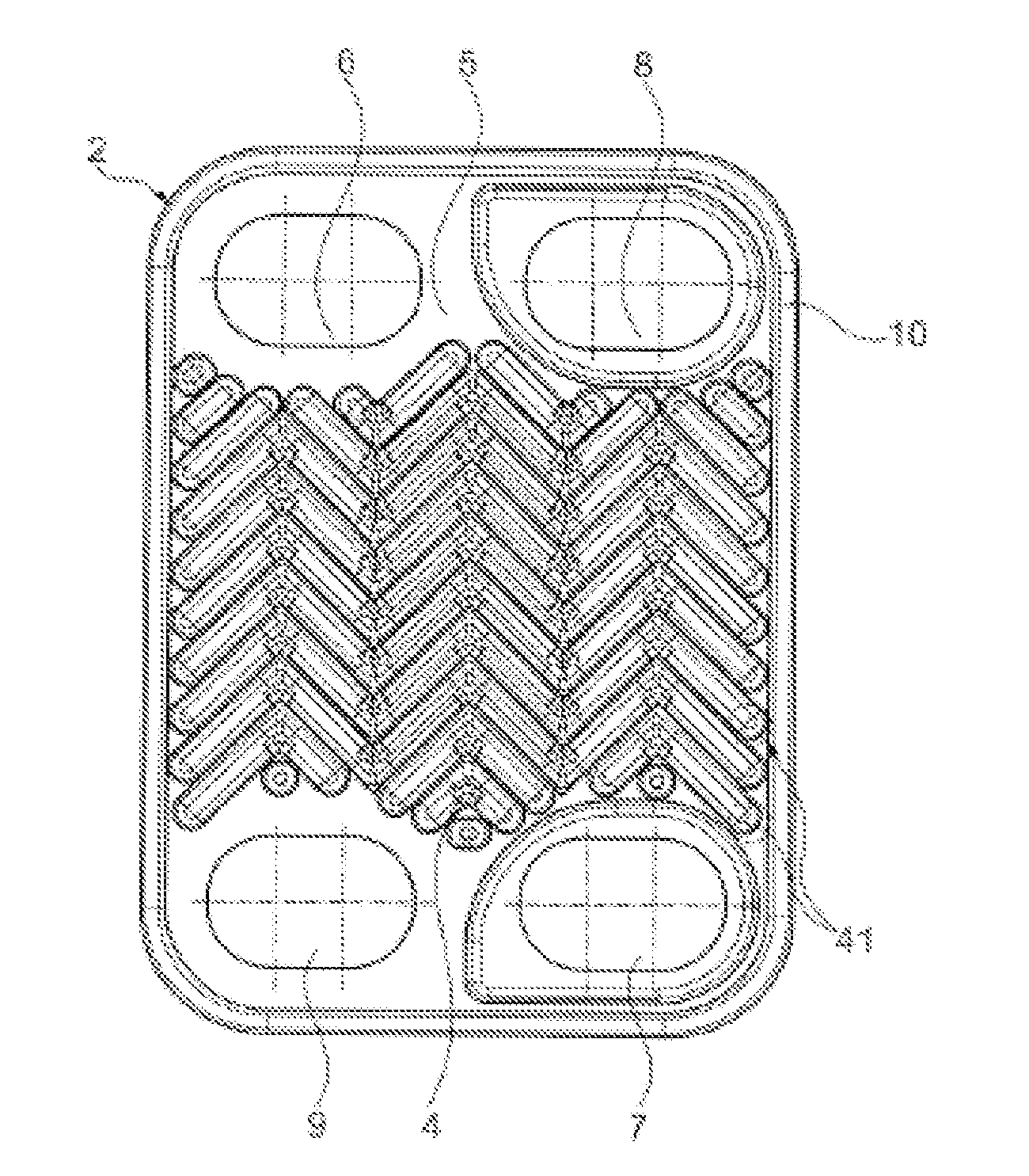
[0022]FIG. 1 shows a first exemplary embodiment of the heat exchanger 1 according to the invention in which a plan view of a first plate 2 having a first plate design is depicted. Here, each of the plates 2 has a corrugated profile 4 of which the corrugations 42 terminate before the edge and which is stamped into a base plate 5. Leadthrough openings 6, 7, 8, 9 are in each case arranged in the vicinity of the edge of the base plates 5. The leadthrough openings 6, 7 and 8, 9 situated diagonally opposite one another form a pair, wherein the leadthrough opening 6 forms the supply for the coolant, whereas the leadthrough opening 7 forms the outflow for the coolant. Correspondingly, the leadthrough opening 9 forms the supply for the medium to be cooled, whereas the leadthrough opening 8 situated diagonally opposite forms the discharge for the medium to be cooled. Here, the leadthrough openings 7, 8 forming the outflow for the media are in each case bordered by a dome. The base plate 5 is ...


PUM


Abstract

The invention relates to a stacked plate heat exchanger, comprising a plurality of elongate plates which are stacked on one another and connected to one another and which have a corrugated profile, which plates have a cavity for leading through a medium to be cooled in the longitudinal direction of the plates and define a further cavity for leading through a coolant, wherein leadthrough openings for supplying or discharging the medium to be cooled or the coolant are formed approximately in the end regions of each elongate plate and each elongate plate is surrounded by a bent-off edge, wherein an nth corrugation of the corrugated profile of each plate is drawn close to the edge, preferably into the edge, whereas the other corrugations of the corrugated profile of the plate terminate before the edge, where n=2, 3, 4 etc.

Description

TECHNICAL FIELD[0001]The invention relates to a stacked plate heat exchanger in accordance with the preamble of claim 1.PRIOR ART[0002]In cooler manufacture, stacked plate heat exchangers are sufficiently well known which cool air which is supplied to a combustion engine by means of an oil coolant or air cooling. DE 43 14 808 A1 discloses a plate heat exchanger, in particular an oil / coolant cooler, which has elongate plates which are stacked on one another and whose peripheral edges lie against one another. The plates of the heat exchanger all have the same shape. The plates have locally turbulence generating elevations in the form of knobs or sealing embossments. However, internal fittings in the form of turbulence inserts or sealing washers are also known.[0003]DE 10 2004 036 951 A1 shows a heat exchanger which is constructed from identical plates which are stacked above one another, wherein each plate has a bent edge. In each case two plates lying above one another here form a ca...

Claims


Application Information

Patent Timeline
Patent Type & Authority Applications(United States)
IPC IPC(8): F28D9/00F28F3/02
CPCF28F3/025F28D9/0062F28F3/046F28D9/005
Inventor DRANKOW, ANDREASRICHTER, JENSHOFMANN, HERBERT
Owner MAHLE INT GMBH
Why Eureka
Try Eureka