Cable Repair Splice

a cable and cable technology, applied in the field of electrical cables, can solve the problems of electrical cables being nicked, cut, severed, abraded, etc., and/or otherwise damaged during use, and the electrical cable is no longer capable of transmitting data signals,

Active Publication Date: 2015-04-09
TYCO ELECTRONICS (UK) LTD +2
View PDF14 Cites 17 Cited by
  • Summary
  • Abstract
  • Description
  • Claims
  • Application Information

AI Technical Summary

Problems solved by technology

Electrical cables may be nicked, cut, severed, abraded, and / or otherwise damaged during use.
Abrasion may result from an electrical cable rubbing against a neighboring object.
Damage to an electrical cable may impair operation of the cable.
For example, damage to an electrical cable may interrupt the electrical paths of the cable such that the electrical cable is no longer capable of conveying data signals between the components.
When some known electrical cables are damaged, the cable is replaced instead of being repaired.
Such a change in impedance may cause the electrical cable to experience signal losses, unwanted reflections, and / or the like along the location of the repair.
Replacing electrical cables is difficult, costly, and / or time consuming.
For relatively long cables and / or cables that are routed along complex paths and / or through tight spaces, removing the damaged cable and routing the undamaged cable may be particularly difficult, time-consuming, and / or costly.
Moreover, the added cost of the undamaged cable may cause replacement of an electrical cable to be more costly than repair.

Method used


Image

  • Cable Repair Splice
  • Cable Repair Splice
  • Cable Repair Splice

Examples


Embodiment Construction

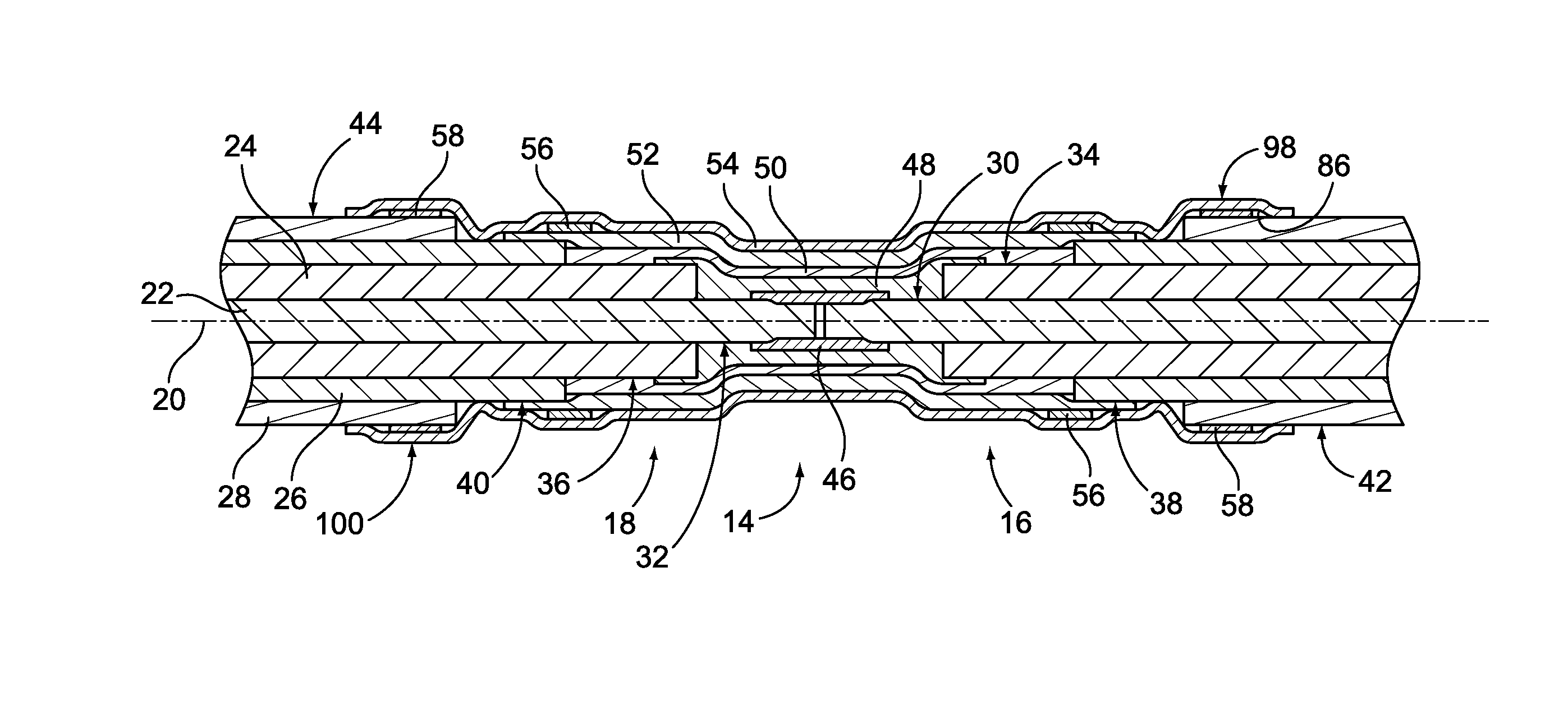
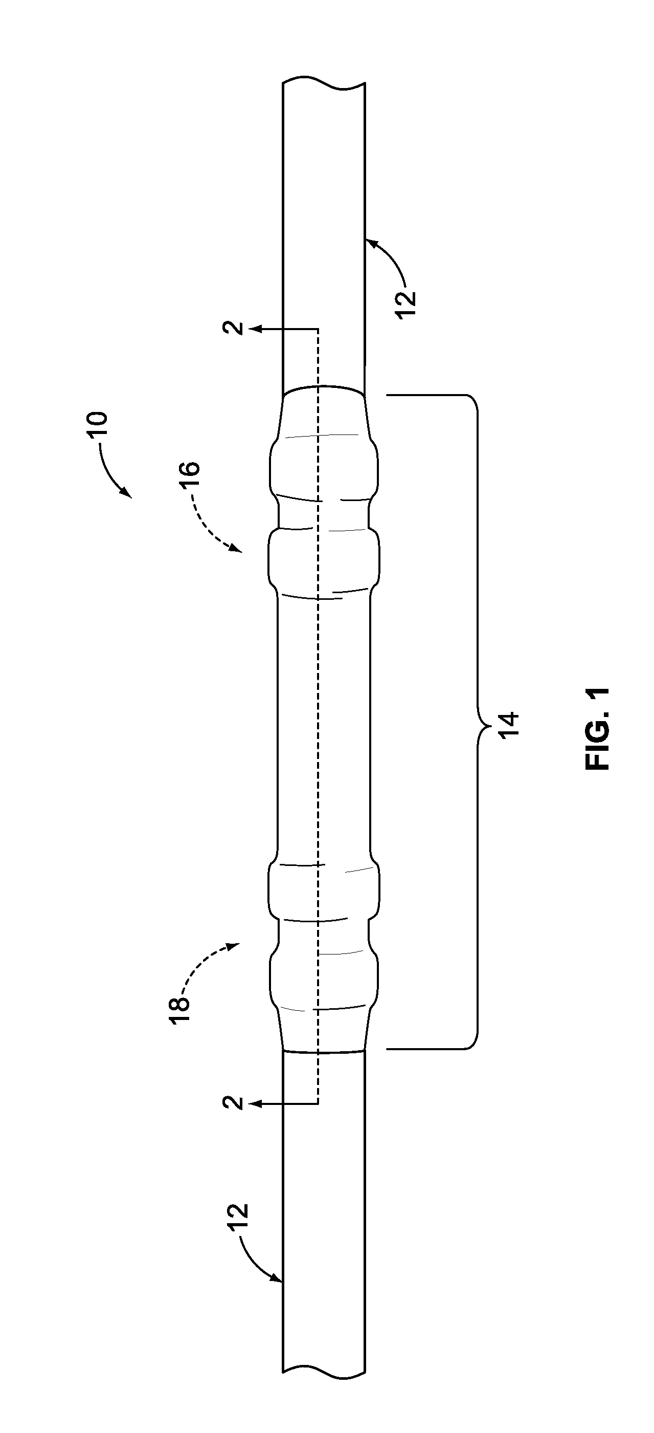
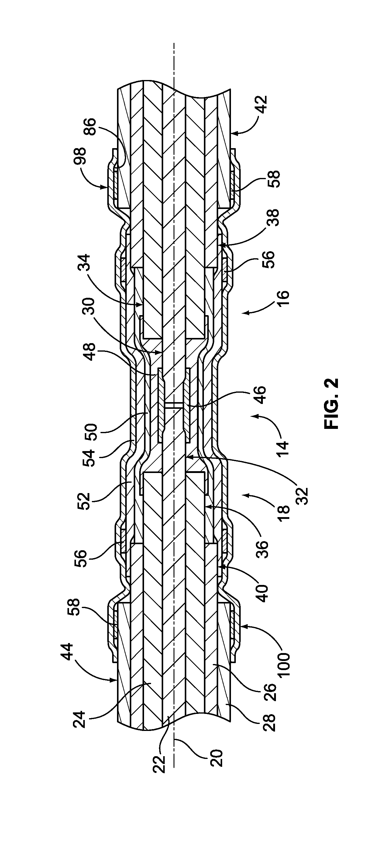
[0021]FIG. 1 is a perspective view of an exemplary embodiment of a spliced cable assembly 10. The assembly 10 includes a coaxial cable 12 and a splice 14 that is used to repair the coaxial cable 12. In an exemplary embodiment, the coaxial cable 12 has been completely severed across the length thereof into opposing ends 16 and 18 that were electrically and mechanically disconnected from each other before the splice 14 was installed. The splice 14 electrically and mechanically connects the ends 16 and 18 together such that the splice 14 reestablishes the electrical and mechanical connection between the cable ends 16 and 18. The splice 14 thereby reestablishes the electrical paths of the coaxial cable that were interrupted when the coaxial cable 12 was severed. As will be described below, the splice 14 is configured to match an impedance of the coaxial cable 12 as closely as possible (e.g., within a predetermined percentage or ohm value). The splice 14 is configured to reduce or preven...


PUM


Abstract

A splice kit is provided for repairing a cable having a central conductor, an insulator surrounding the central conductor, an outer conductive sheath surrounding the insulator, and a jacket surrounding the outer conductive sheath. The splice kit includes a central conductor joint that is electrically conductive and is configured to engage the central conductor of the cable such that the central conductor joint defines a portion of an electrical path of the central conductor. The splice kit also includes a dielectric insert configured to at least partially surround the central conductive joint and the central conductor of the cable, and an outer sheath joint that is electrically conductive and is configured to at least partially surround the dielectric insert. The outer sheath joint is configured to be electrically connected to the outer conductive sheath of the cable such that the outer sheath joint defines a portion of an electrical path of the outer conductive sheath. The splice kit further includes a jacket joint configured to at least partially surround the outer sheath joint and the jacket of the cable.

Description

BACKGROUND OF THE INVENTION[0001]The subject matter described and / or illustrated herein relates generally to electrical cables.[0002]Electrical cables are widely used for interconnecting components that are spaced apart from each other. Some typical examples of electrical cables include coaxial cables, triaxial cables, twin axial cables, and quadrax cables. Electrical cables may be nicked, cut, severed, abraded, and / or otherwise damaged during use. For example, an electrical cable may be cut or completely severed by a relatively sharp object. Electrical cables can also be completely severed by blunt objects that exert enough force to snap the cable. Abrasion may result from an electrical cable rubbing against a neighboring object. A kink is yet another example of cable damage. Damage to an electrical cable may impair operation of the cable. For example, damage to an electrical cable may interrupt the electrical paths of the cable such that the electrical cable is no longer capable o...

Claims


Application Information

Patent Timeline
Patent Type & Authority Applications(United States)
IPC IPC(8): H01R4/72
CPCH01R4/72H01R9/0503H01R2103/00H02G1/14H02G1/16H02G15/1806
Inventor POPE, MARTINBRIERE, THOMAS A.MOORE, ROBERT P.PRZYBYLSKA, NINA
Owner TYCO ELECTRONICS (UK) LTD
Why Eureka
Try Eureka