Self-blocking descender-belay device

a descender and self-blocking technology, which is applied in the field of self-blocking descender-belay devices, can solve the problems of inability to fulfill the self-blocking function, inability to deliberately reduce the braking of users, and inability to stop the movement of descent, so as to achieve the effect of great ease of cam spacing and great ease of cam displacemen

Inactive Publication Date: 2015-04-09
ETAB LUDGER SIMOND
View PDF30 Cites 2 Cited by
  • Summary
  • Abstract
  • Description
  • Claims
  • Application Information

AI Technical Summary

Benefits of technology

[0018]It will be appreciated that these two functions are contradictory, in that easy paying-out of the rope needs great ease of spacing of the cam from the braking nose, whereas secure blocking requires great ease of displacement of the cam towards the braking nose.

Problems solved by technology

This results in braking of the movement of descent.
However, it is found in this device that the automatic triggering of the braking requires tension of the rope which is sufficiently sudden and strong to drive the cam against its return spring.
In the presence of reduced tension, or relatively slow application of the tension of the rope, the blocking of the rope does not take place, and the self-blocking function is not fulfilled.
On the other hand, the deliberate reduction of braking by the user is not regular.
Firstly, by using the cam manoeuvring unit in order to allow the rope to pay out with braking, the paying-out of the rope is relatively jerky.
Secondly, in order to supply a climber with free rope, it is necessary to inhibit the braking.
This leads the user to act directly with his hand on the cam, in order to space it from the braking nose, with the risk of forgetting to release the hand when blocking is necessary.
Thus, this device does not make it possible to control easily the braking of the rope in order to allow it to be paid out regularly with or without a load.

Method used


Image

  • Self-blocking descender-belay device
  • Self-blocking descender-belay device
  • Self-blocking descender-belay device

Examples


Embodiment Construction

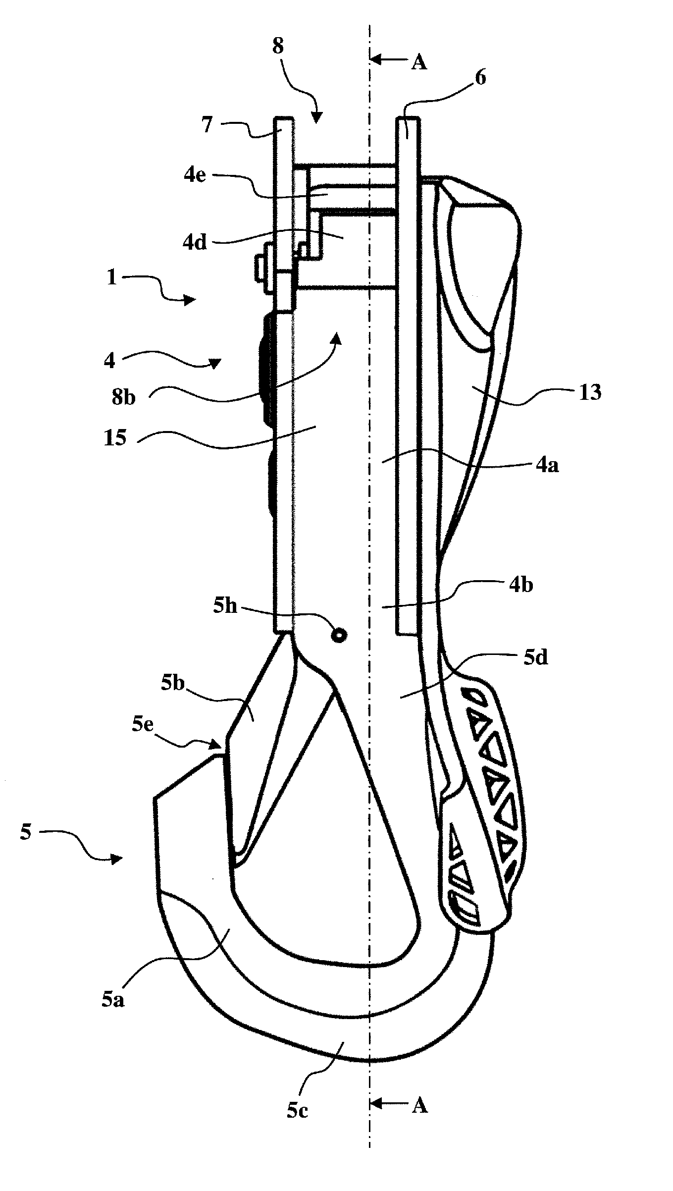
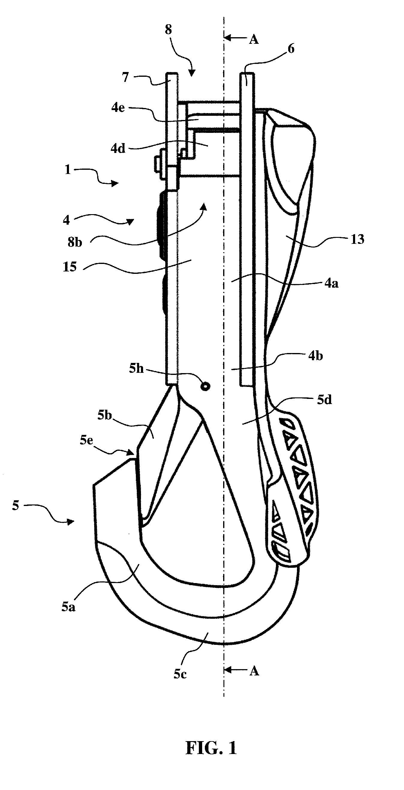
[0058]In the embodiment illustrated in FIGS. 1 to 12, the self-blocking descender-belay device 1 according to the invention permits control of the paying-out of a rope 3 (FIGS. 5 to 7) in a paying-out direction which is illustrated by the arrow F. Thus, the rope 3 comprises an input end 3A, an output end 3B, and an intermediate section 3C which passes through the self-blocking descender-belay device 1.

[0059]In general, the self-blocking descender-belay device 1 comprises a connection device 4 and coupling means 5.

[0060]The connection device 4 is formed so as to ensure a connection with a rope 3, whilst controlling the sliding or blocking of the rope 3 in the connection device 4.

[0061]The coupling means 5 are formed so as to permit the selective coupling of the descender-belay device 1 either to a fixed point, or to the harness of a user.

[0062]The connection device 4 comprises a connection body 4a with a proximal end 4b which is connected to the coupling means 5.

[0063]The connection ...


PUM


Abstract

The self-blocking descender-belay device (1) according to the invention comprises:
    • a first lateral guide flange (6) for the rope, comprising a braking nose (4e),
    • a second lateral guide flange (7) for the rope, which is separated from the first flange (6) by a transverse gap (8) for passage of the rope, and can be displaced between a spaced position for putting into place and removal of a rope, and a closed position in which the rope is trapped in the transverse gap (8) for passage of the rope,
    • a cam (4d) which is engaged between the first and second flanges (6, 7) and is mobile towards and away from the braking nose (4e), and is thrust towards the braking nose (4e) by a cam return spring,
    • the transverse gap (8) for passage of the rope extending between a rope input in the vicinity of the braking nose (4e), and a rope output opposite,
    • the rope output having a large opening such as to permit free orientation of the rope output end between a blocking orientation in which the rope surrounds the cam (4d), and a release orientation in which the rope passes through the transverse gap (8) for passage of the rope directly, and without thrusting the cam (4d) towards the braking nose (4e).

Description

TECHNICAL FIELD OF THE INVENTION[0001]The present invention relates to a self-blocking descender-belay device which is designed to be used to control the paying-out of a rope, for example for the descent of a person down a rope, or for belaying of a person.[0002]Various descender-belay device structures are already known, for example such as that which is described in document EP 0 688 581 B1.[0003]A known descender-belay device of this type comprises:[0004]a first lateral guide flange for the rope, comprising a braking nose,[0005]a second lateral guide flange for the rope, which is separated from the first flange by a transverse gap for passage of the rope, and can be displaced between a spaced position for putting into place and removal of the rope, and a closed position in which the rope is trapped in the transverse gap for passage of the rope,[0006]a cam which is engaged between the first and second flanges and is mobile towards and away from the braking nose,[0007]a cam manoeuv...

Claims


Application Information

Patent Timeline
Patent Type & Authority Applications(United States)
IPC IPC(8): A62B1/14A63B29/02
CPCA63B29/02A62B1/14
Inventor LEFEBVRE, PATRICKMANSUY, MATHIEUMOLLIEX, ROMAIN
Owner ETAB LUDGER SIMOND
Why Eureka
Try Eureka