Eureka AIR delivers breakthrough ideas for toughest innovation challenges, trusted by R&D personnel around the world.

Methods for producing polysilicon resistors

Active Publication Date: 2015-04-09
INFINEON TECH AG
View PDF17 Cites 5 Cited by
  • Summary
  • Abstract
  • Description
  • Claims
  • Application Information

AI Technical Summary

Benefits of technology

The patent text describes a method for making a polysilicon resistor device by creating a layer of polysilicon and then implanting dopant atoms into it. The dopant atoms can be deep energy level donors or shallow energy level donors. Annealing the polysilicon layer after the implantation can cause the dopant atoms to diffuse and create the desired resistor effect. The method allows for precise placement and control of the dopant atoms, resulting in a more precise and accurate polysilicon resistor device.

Problems solved by technology

During operation of the power transistors, a wide variety of switching states occur, in which in part very large power losses are converted into heat.
Such switching states associated with large power losses are critical since the temperature rises greatly in this case and the power transistors can be destroyed by overheating.
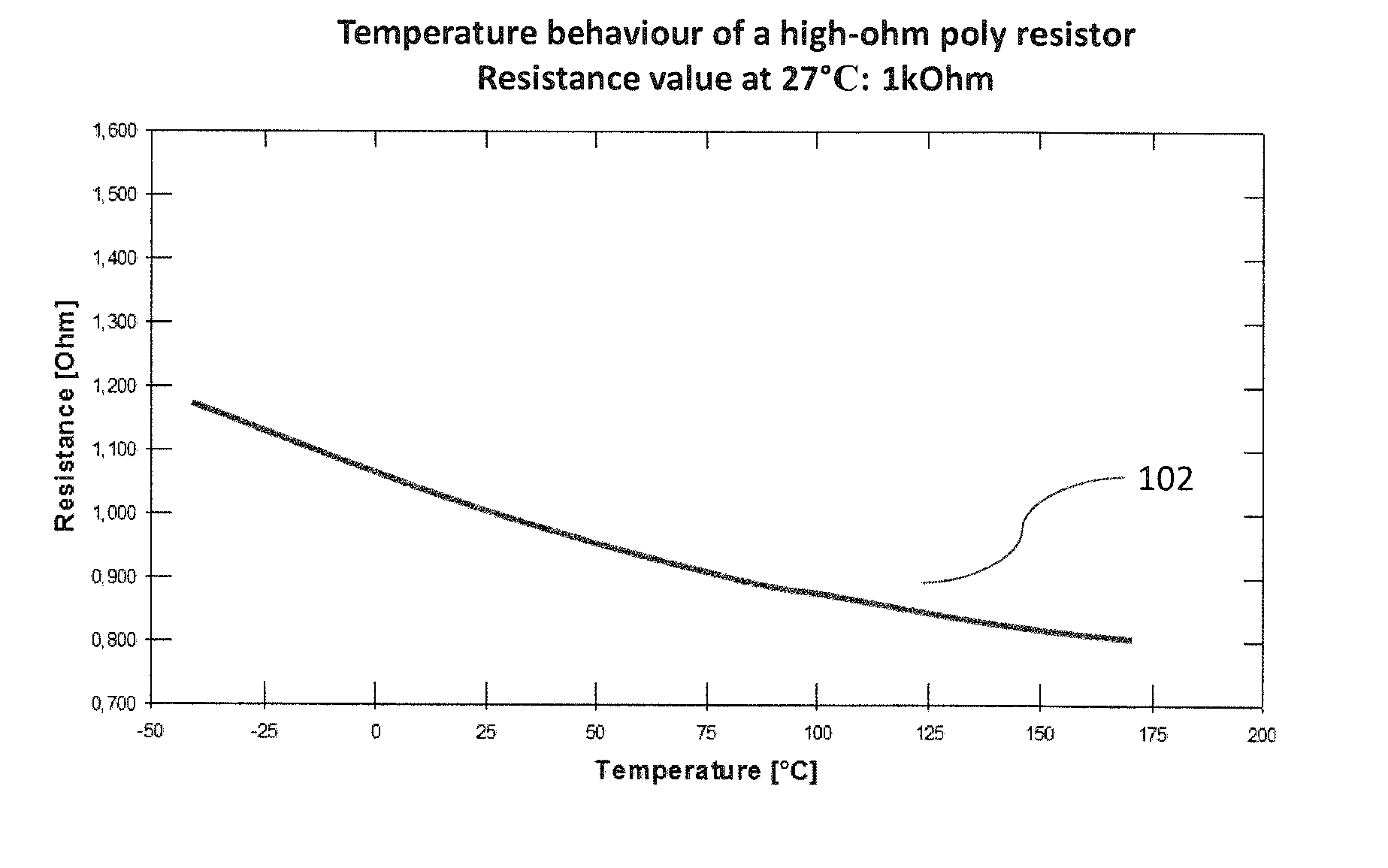
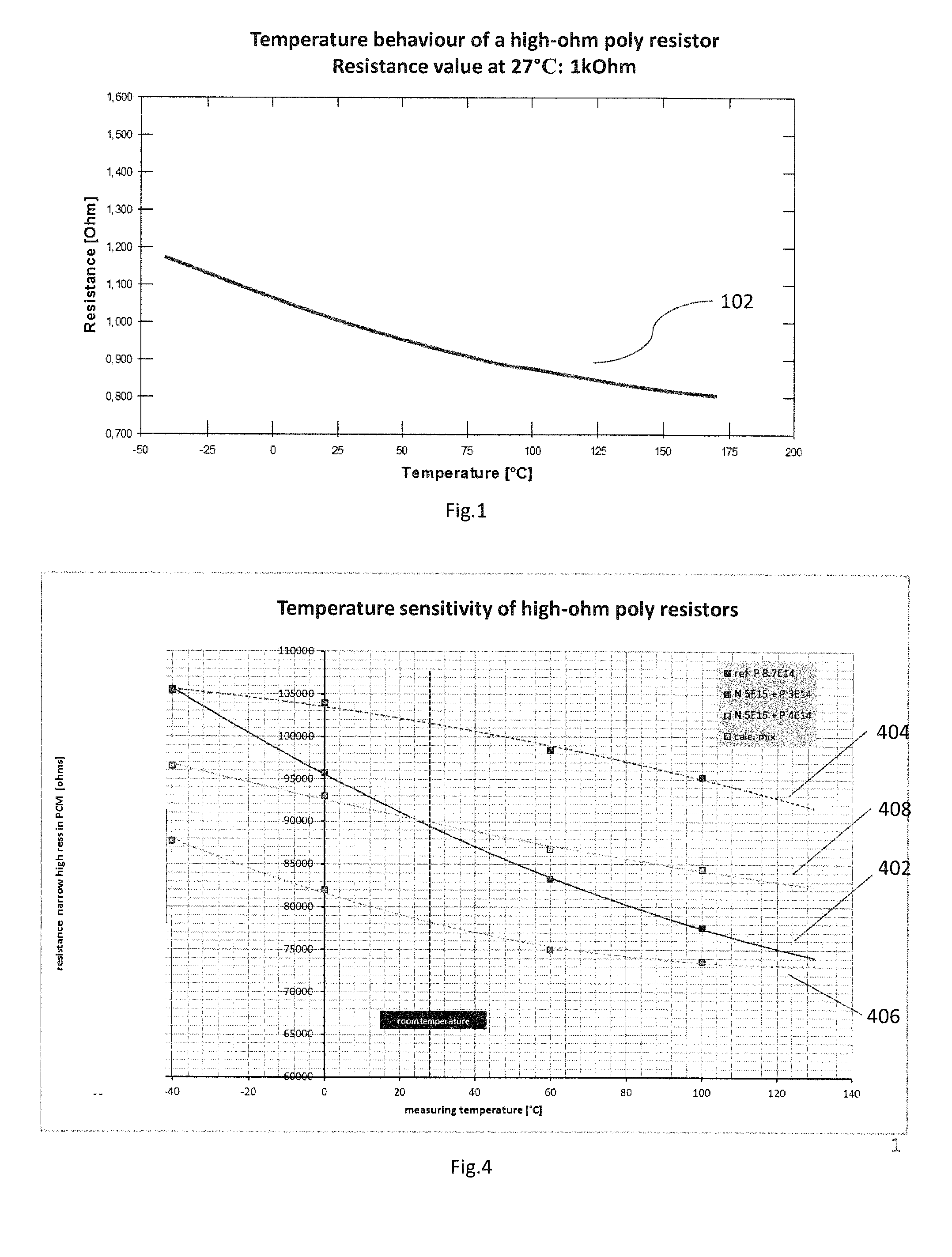
However, this concept with a resistance temperature sensor often fails in practice because of excessively large manufacturing variations with which a resistance temperature sensor of this type can be produced, since the absolute value of the resistance cannot be used as a turn-off threshold meaningfully.

Method used


Image

  • Methods for producing polysilicon resistors
  • Methods for producing polysilicon resistors
  • Methods for producing polysilicon resistors

Examples


Embodiment Construction

[0027]In the following detailed description, reference is made to the accompanying drawings, which form a part hereof, and in which is shown by way of illustration specific embodiments in which the disclosure may be practiced. In this regard, directional terminology, such as “front,”“back,”“leading,” etc., is used with reference to the orientation of the figures being described. Because components of embodiments can be positioned in a number of different orientations, the directional terminology is used for purposes of illustration and is in no way limiting. It is to be understood that other embodiments may be utilized and structural or logical changes may be made without departing from the scope of the present disclosure. The following detailed description, therefore, is not to be taken in a limiting sense, and the scope of the present disclosure is defined by the appended claims.

[0028]It is to be understood that the features of the various exemplary embodiments described herein ma...


PUM


Abstract

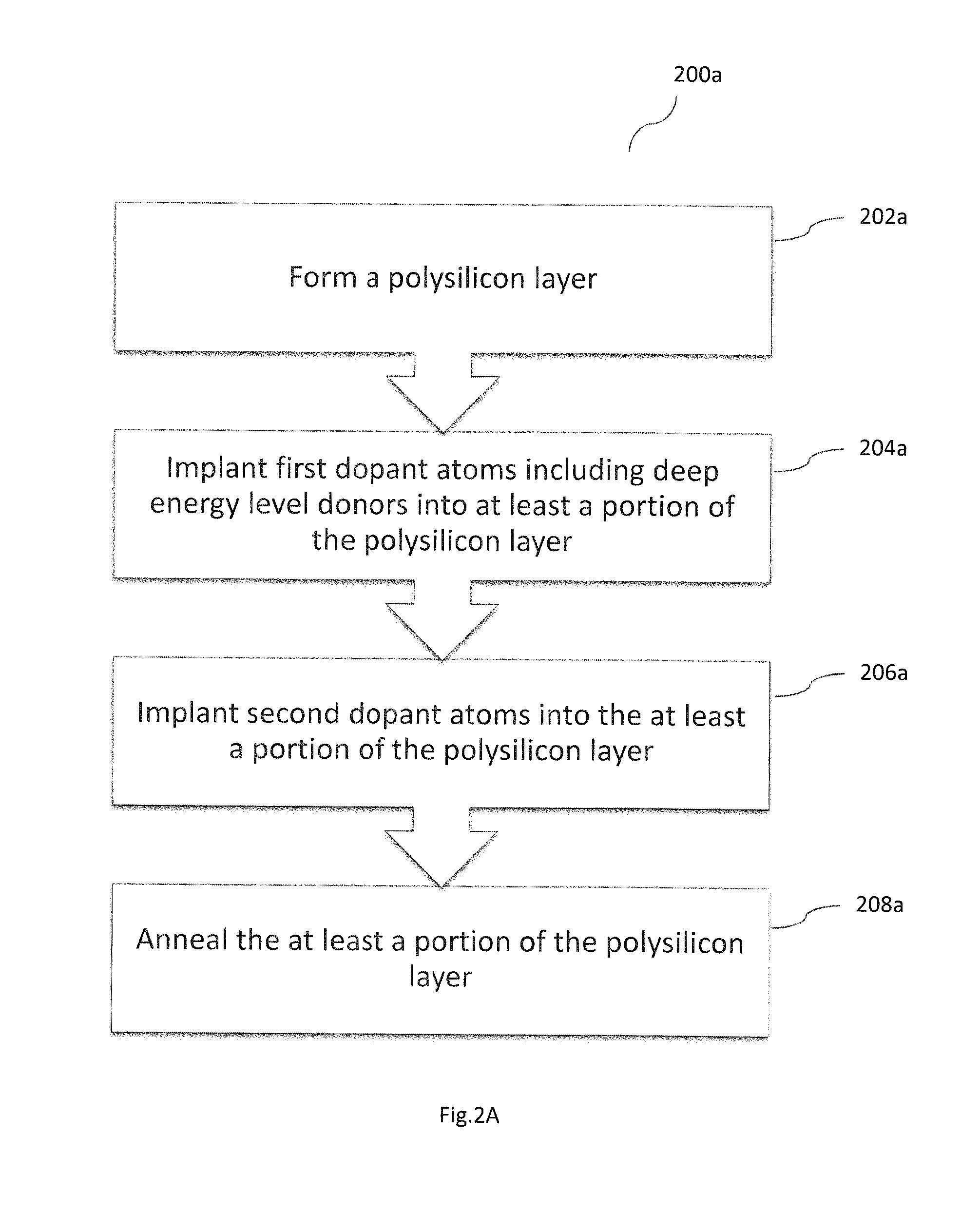
A method for producing a polysilicon resistor device may include: forming a polysilicon layer; implanting first dopant atoms into at least a portion of the polysilicon layer, wherein the first dopant atoms include deep energy level donors; implanting second dopant atoms into said at least a portion of said polysilicon layer; and annealing said at least a portion of said polysilicon layer.

Description

TECHNICAL FIELD[0001]The disclosure relates to methods for manufacturing polysilicon resistors in semiconductor components, especially for producing precise polysilicon resistors, e.g. resistance temperature sensors, and for producing polysilicon resistors having well-controlled temperature coefficients.BACKGROUND[0002]With the introduction of the silicon planar technology, not only the active components like NMOS transistors (N-type metal-oxide-semiconductor transistors), PMOS transistors (P-type metal-oxide-semiconductor transistors) and bipolar transistors, but also the passive components like resistors are required to qualify with the silicon planar technology. The use of polycrystalline silicon, or polysilicon as it is commonly known, as a resistor, is well known in the fabrication of semiconductor devices. Generally polysilicon resistivity either increases or decreases with increasing temperature. This rate of increase is referred to as a temperature coefficient of resistance....

Claims


Application Information

Patent Timeline
IPC IPC(8): H01L49/02
CPCH01L28/20G01K7/186H01L21/266H01L27/0802
Inventor GRUBER, HERMANNGROSS, THOMASIRLBACHER, WERNERZUNDEL, MARKUSVON BORCKE, MATHIASSCHULZE, HANS JOACHIM
Owner INFINEON TECH AG
Why Eureka
Eureka Blog
Learn More