Solar cell apparatus

a solar cell and solar cell technology, applied in electrical devices, photovoltaics, semiconductor devices, etc., can solve the problems of deterioration of the performance of the solar cell panel, and achieve the effect of wide lighting area

Inactive Publication Date: 2015-04-16
LG INNOTEK CO LTD
View PDF1 Cites 0 Cited by
  • Summary
  • Abstract
  • Description
  • Claims
  • Application Information

AI Technical Summary

Benefits of technology

[0012]As described above, according to the solar cell apparatus of the embodiment, the refractive part is provided in the transmission area. Accordingly, the light incident into the transmission area is refracted to the non-transmission area through the refractive part.
[0013]In detail, the light refracted by the refractive part is output to the lower portion of the substrate and the non-transmission area.
[0014]Therefore, the solar cell apparatus according to the embodiment can supply light to both of the transmission area and the non-transmission area. In other words, when the solar cell apparatus according to the embodiment is used as a window, the solar cell apparatus according to the embodiment can supply the light to both of the transmission area and the non-transmission area.
[0015]Accordingly, the solar cell apparatus according to the embodiment can supply light to the non-transmission area having the solar cells, as well as the transmission area, so that the solar cell apparatus may have a wide lighting area.

Problems solved by technology

In other words, when the performance of the solar cell panel is deteriorated, current flows through the diode.

Method used


Image

  • Solar cell apparatus
  • Solar cell apparatus
  • Solar cell apparatus

Examples


Embodiment Construction

[0025]In the following description of the embodiments, it will be understood that, when a panel, a bar, a frame, a substrate, a recess, or a film is referred to as being “on” or “under” another panel, bar, frame, substrate, recess, or film, it can be “directly” or “indirectly” on the other panel, bar, frame, substrate, recess, or film, or one or more intervening layers may also be present. Such a position of the element described with reference to the drawings. The thickness and size of each element shown in the drawings may be exaggerated, omitted or schematically drawn for the purpose of convenience or clarity. In addition, the size of elements does not utterly reflect an actual size.

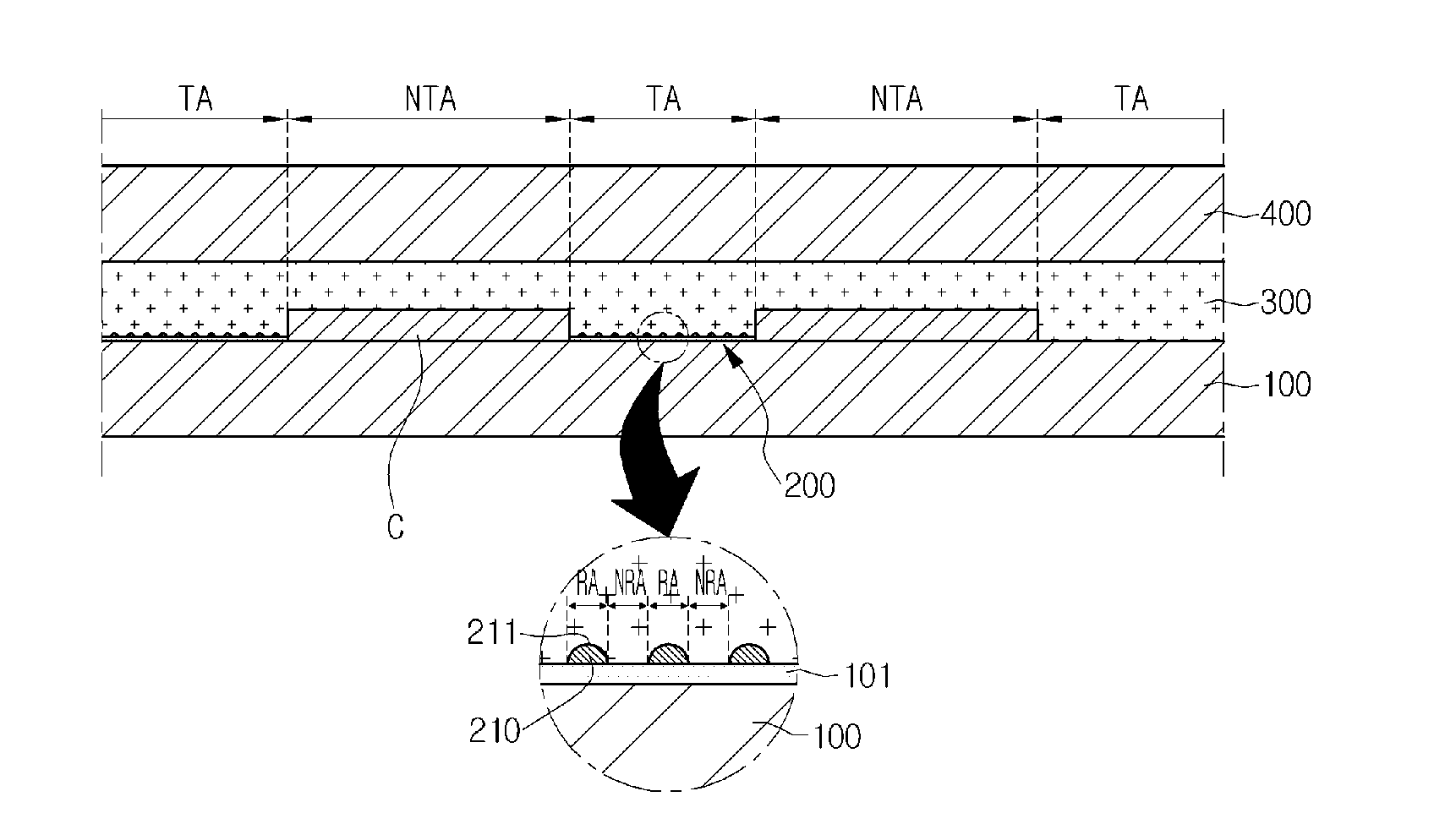
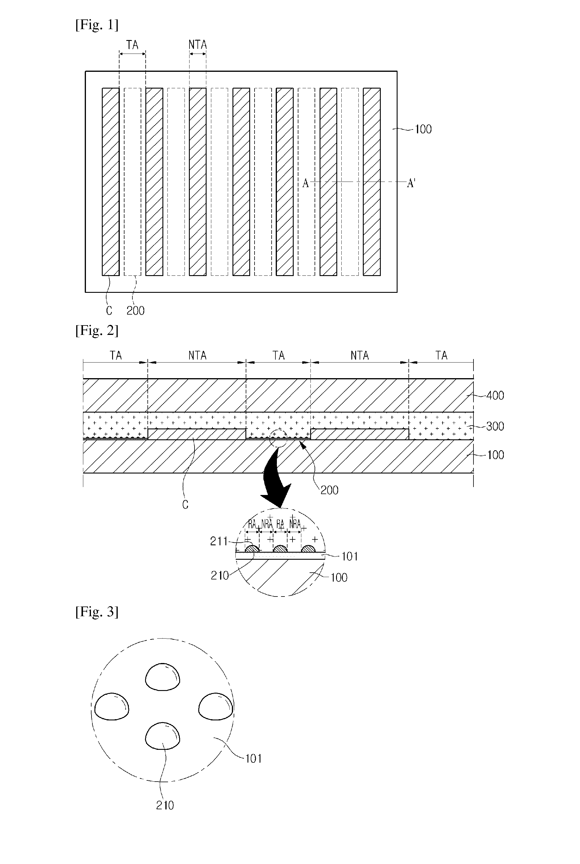
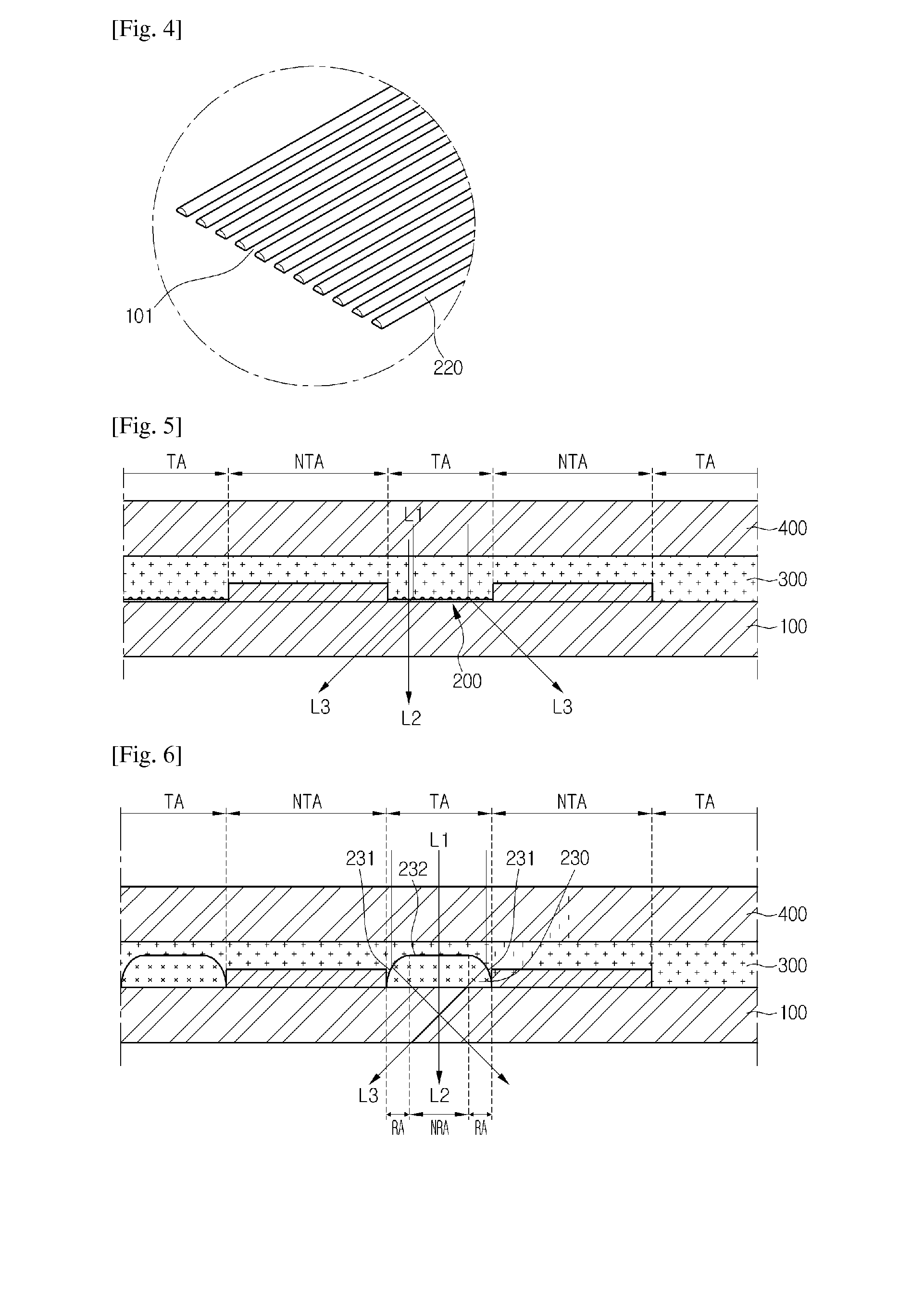
[0026]FIG. 1 is a plan view showing a solar cell apparatus according to one embodiment. FIG. 2 is a sectional view taken along line A-A′ of FIG. 1. FIG. 3 is a view showing one shape of a refractive part. FIG. 4 is a view showing one shape of a refractive part. FIG. 5 is a sectional view showing the p...


PUM


Abstract

Disclosed is a solar cell apparatus. The solar cell apparatus includes a substrate including a transmission area and a non-transmission area extended in one direction, respectively, and disposed in parallel to each other, a solar cell disposed in the non-transmission area, and a refractive part provided in the transmission area and refracting at least a portion of an incident light to the non-transmission area.

Description

TECHNICAL FIELD[0001]The embodiment relates to a solar cell apparatus.BACKGROUND ART[0002]Solar cell apparatuses to convert the solar light into electrical energy include solar cells panels, diodes, and frames.[0003]The solar cell panel has the shape of a plate. For example, the solar cell panel has the shape of a rectangular plate. The solar cell panel is provided inside the frame. Four lateral sides of the solar cell panel are provided inside the frame.[0004]The solar cell panel receives the solar light and converts the solar light into the electrical energy. The solar cell panel includes a plurality of solar cells. In addition, the solar cell panel may further include a substrate, a film, or a protective glass to protect the solar cells.[0005]In addition, the solar cell panel includes bus bars coupled to the solar cells. The bus bars are extended on the top surface of the outermost solar cells so that the bus bars are connected to wirings, respectively.[0006]The diode is connecte...

Claims


Application Information

Patent Timeline
Patent Type & Authority Applications(United States)
IPC IPC(8): H01L31/054
CPCH01L31/0543H01L31/048Y02E10/52H01L31/042H02S40/22
Inventor LEE, DONG KEUN
Owner LG INNOTEK CO LTD
Why Eureka
Try Eureka