Electronic part manufacturing method and electronic part manufactured by the method
a manufacturing method and electronic technology, applied in the direction of transfer patterning, conductive pattern formation, transportation and packaging, etc., can solve the problems of high manufacturing time, high manufacturing cost, and difficulty in ensuring the correct position of each layer, so as to reduce the number of superpose printing steps, eliminate defects, and improve production efficiency
- Summary
- Abstract
- Description
- Claims
- Application Information
AI Technical Summary
Benefits of technology
Problems solved by technology
Method used
Image
Examples
example 1
Formation of BGSC Organic Transistor Element
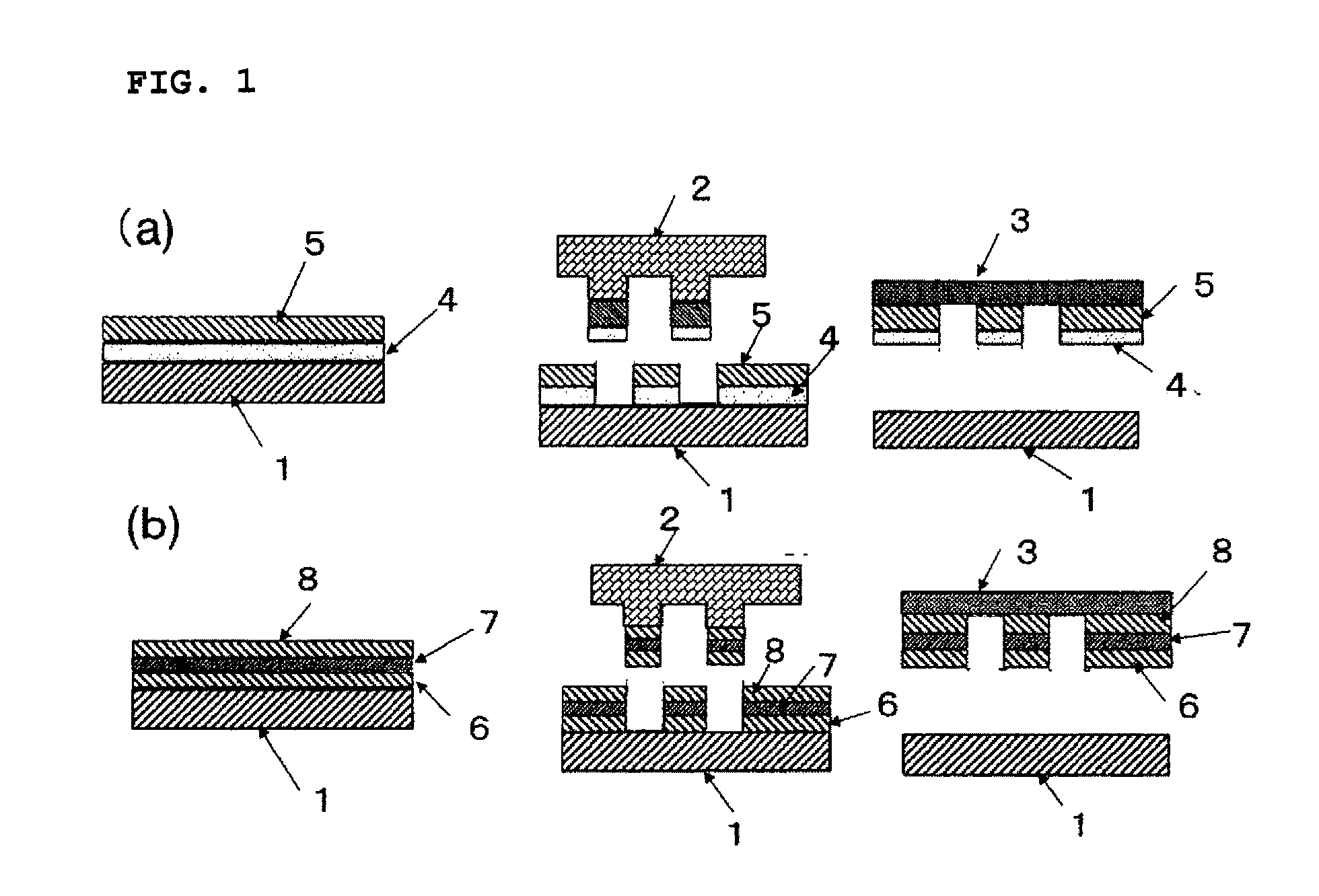
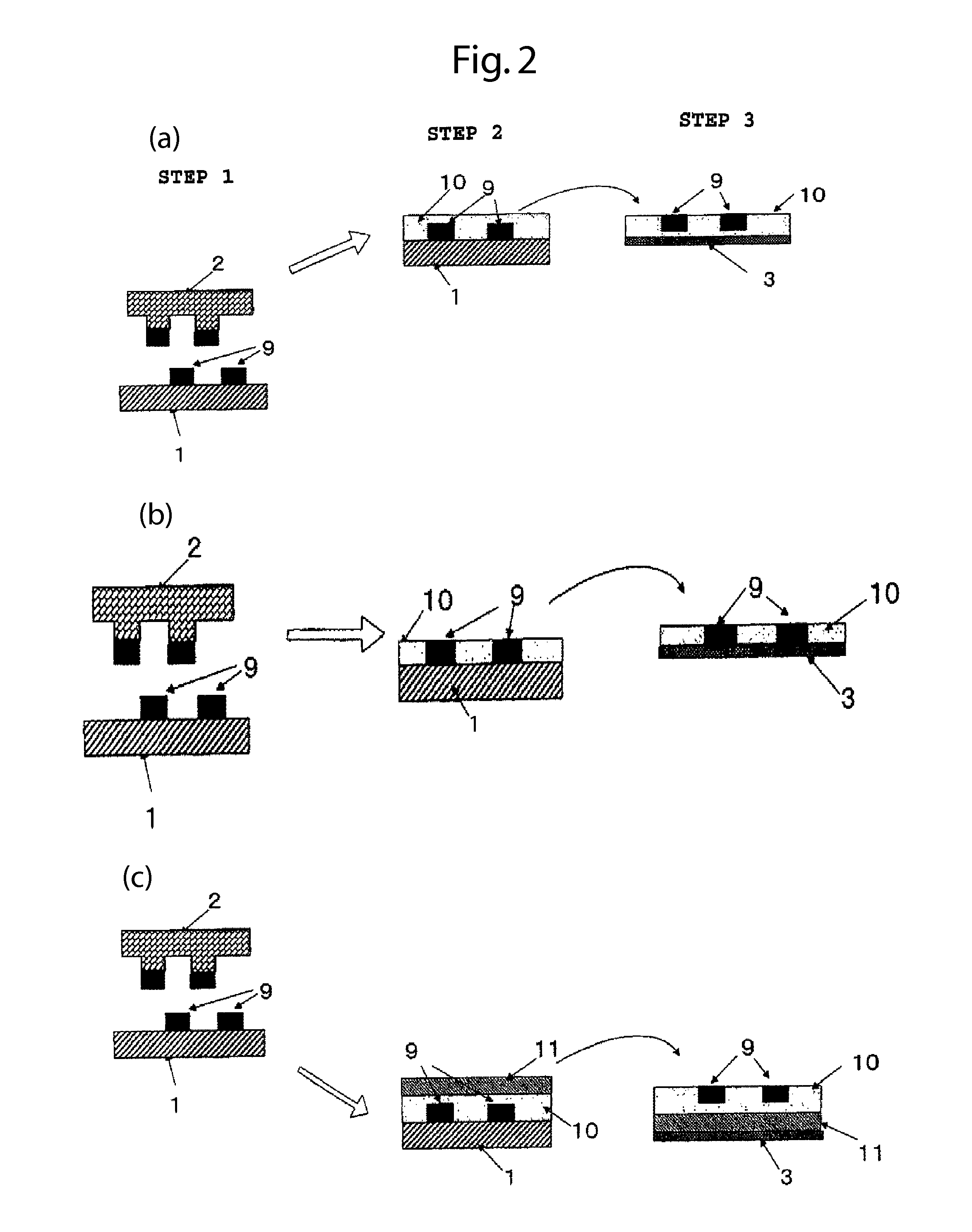
[0061]As shown in FIG. 3, a source / drain electrode pattern 9s / 9d was formed on a transfer plate 1 (3-1 of FIG. 3). The electrode pattern was formed using a conductive ink containing a fluorine-based surfactant. Then, a semiconductor ink containing P3HT as a main component was uniformly applied to the transfer plate 1, on which the pattern had been formed, using a capillary coater so that the thickness at a maximum after evaporation of the solvent was smaller than the thickness of the electrode, thereby forming an ink film layer 13 of P3HT (3-2 of FIG. 3). In this case, coating of the organic semiconductor ink on the electrode pattern was not observed.
[0062]Then, the organic semiconductor ink, excluding the organic semiconductor ink pattern remaining between the source and drain, was removed from the transfer plate 1 to leave the source / drain electrode pattern by the relief offset method using the same pattern as the relief plate for formin...
example 2
Method for Manufacturing BGBC-Type Organic Transistor Element
[0064]A method for manufacturing a BGBC-type MIS organic transistor element is shown in FIG. 4.
(1) Formation of Gate Electrode
[0065]A relief offset printing conductive ink containing silver nano particles dispersed therein was uniformly applied by a capillary coater to the entire surface of a transfer plate 1 having a smooth releasing surface composed of a silicone resin. Then, a glass relief plate (not shown) was pressed on the ink surface to remove an excessive ink, forming a gate electrode pattern 9g on the transfer plate 1. Then, an insulating ink containing an epoxy resin and a polyvinyl phenol resin as main components was uniformly applied to the gate pattern 9g on the transfer plate 1 by using a capillary coater, forming an insulating ink film layer 10i. After being allowed to stand for about 1 minute, the insulating film ink and the gate electrode pattern in a semidried state were reversely transferred to a plastic...
example 3
BGBC+Protective Film (with Via)+Pixel Electrode
[0068]As shown in FIG. 5a, a conductive pattern 14 serving as via was formed on a transfer plate having a smooth surface composed of a silicone resin by the relief offset method using a nano silver ink containing a liquid-repellent component including a fluorine-based surfactant. A coating film of a projective film forming ink containing an epoxy resin as a main component was uniformly applied to the nano-silver ink pattern previously formed so that the thickness was smaller than that of at least the conductive pattern, thereby forming a protective film ink layer 15. In this case, adhesion of the ink to the pattern was not observed. The protective film forming ink layer and the conductive pattern layer were simultaneously reversely transferred so that the conductive pattern 14 was in contact with the drain electrode 9d of the organic transistor formed in Example 1, followed by sintering at 140° C. for about 30 minutes.
[0069]Then, a patt...
PUM
 Abstract
Description
Claims
Application Information
 - R&D Engineer
- R&D Manager
- IP Professional
- Industry Leading Data Capabilities
- Powerful AI technology
- Patent DNA Extraction
Browse by: Latest US Patents, China's latest patents, Technical Efficacy Thesaurus, Application Domain, Technology Topic, Popular Technical Reports.
© 2024 PatSnap. All rights reserved.Legal|Privacy policy|Modern Slavery Act Transparency Statement|Sitemap|About US| Contact US: help@patsnap.com


