Eureka AIR delivers breakthrough ideas for toughest innovation challenges, trusted by R&D personnel around the world.

Gap adjusting method in trip mechanism of molded case circuit breaker

a technology of trip mechanism and circuit breaker, which is applied in the direction of protective switch details, instruments, protective devices, etc., can solve the problems of color change of elements, high cost of constant current test equipment for applying current, maintenance cost, etc., and achieve the effect of easy adjustment of gaps

Active Publication Date: 2015-04-23
LSIS CO LTD
View PDF3 Cites 3 Cited by
  • Summary
  • Abstract
  • Description
  • Claims
  • Application Information

AI Technical Summary

Benefits of technology

The patent describes a method for adjusting the gap between a bimetal and a crossbar in a trip mechanism of a molded case circuit breaker. The method uses a gap adjusting block and an adjusting screw, making the process easier and simpler. It also reduces the number of additional devices necessary for the adjustment, reducing installation costs. Overall, the method simplifies the process and reduces the cost of equipment.

Problems solved by technology

A current several hundred times higher than a rated current of a product is applied within several seconds for performing the gap adjusting operation according to the standard, and for this reason, quality problems such as a color change of an element and an expansion of a load terminal caused by heat transfer occur.
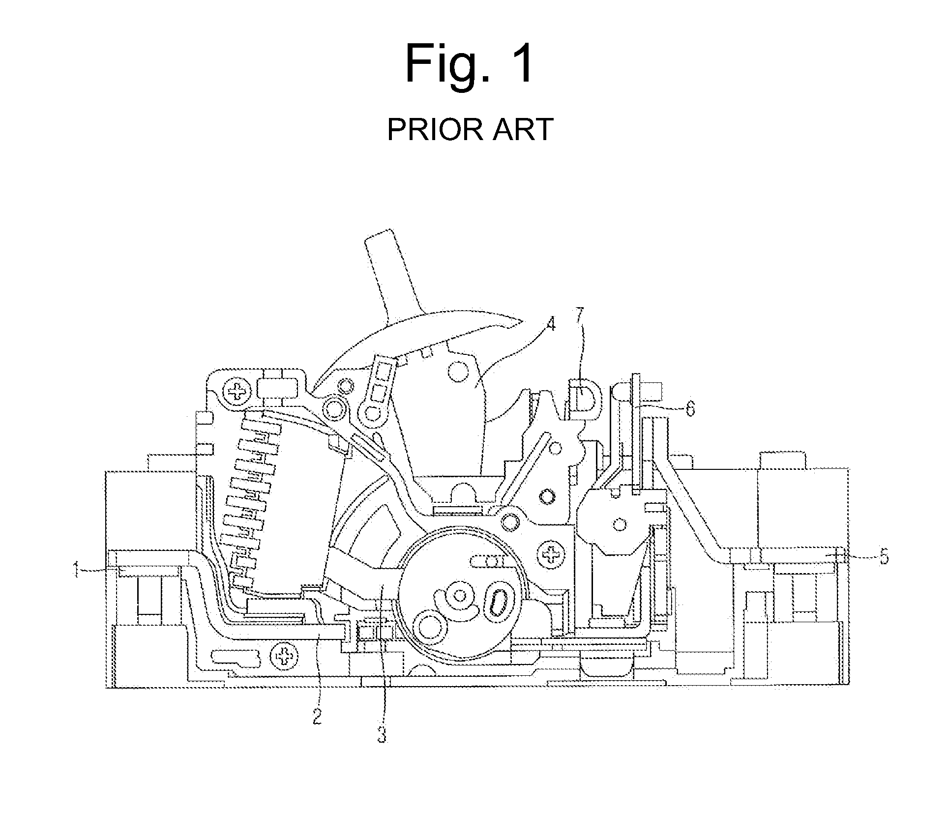
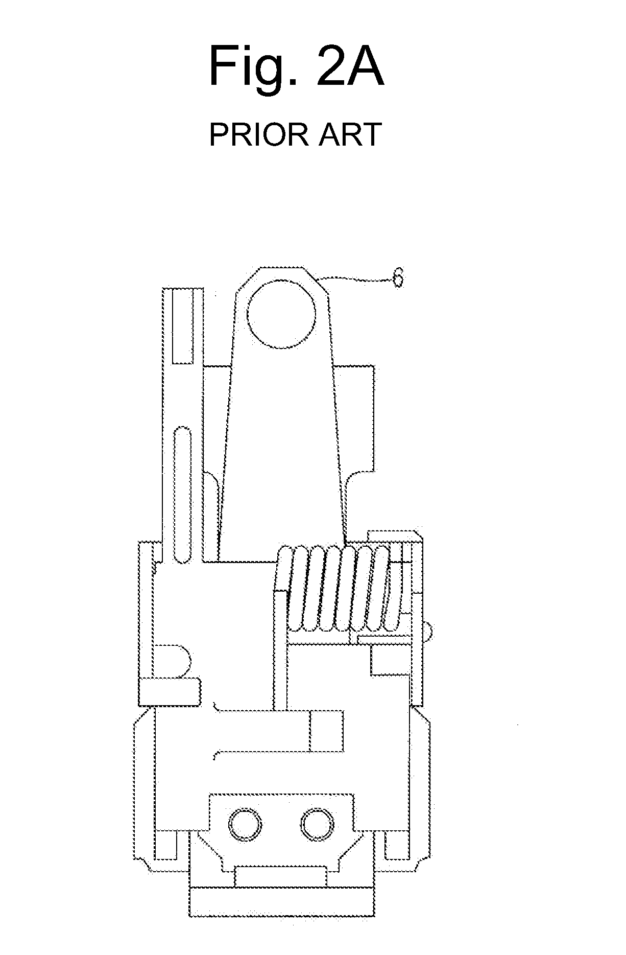
Moreover, much cost for constant current test equipment for applying a current, laser welding equipment and a cooling device for fixing a rivet after a gap is adjusted, and facilities of the cooling device for restoring a bent bimetal after the gap is adjusted is expended, and maintenance cost is also expended.
When a change of a gap is needed due to a 4M change, it is difficult for a worker to easily change an amount of applied current or a time.

Method used


Image

  • Gap adjusting method in trip mechanism of molded case circuit breaker
  • Gap adjusting method in trip mechanism of molded case circuit breaker
  • Gap adjusting method in trip mechanism of molded case circuit breaker

Examples


Embodiment Construction

[0036]Description will now be given in detail of the exemplary embodiments, with reference to the accompanying drawings. For the sake of brief description with reference to the drawings, the same or equivalent components will be provided with the same reference numbers, and description thereof will not be repeated.

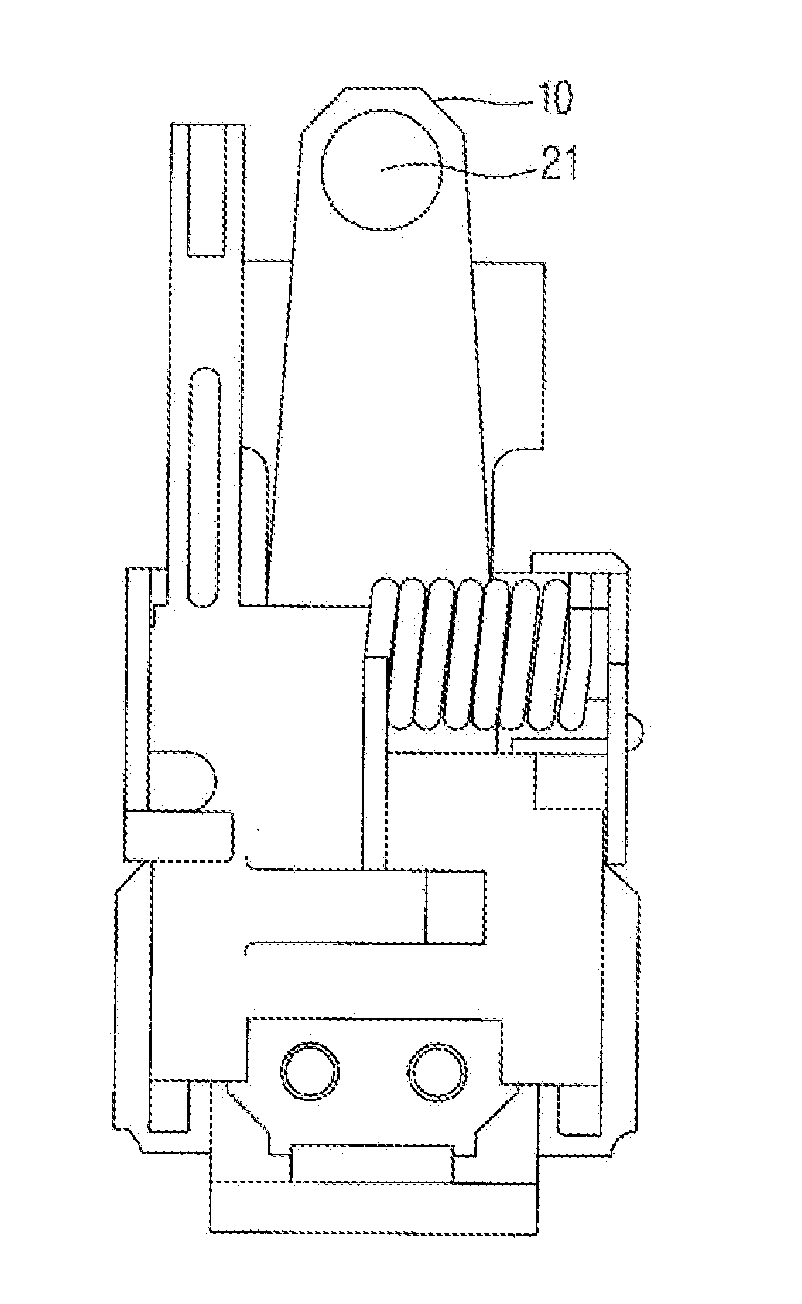
[0037]FIG. 5A and 5B are partial front view and partial side view of a trip mechanism according to an embodiment of the present invention; FIG. 6A and 6B are front view and side view of a bimetal according to an embodiment of the present invention; FIG. 7A and 7B are detailed views of an adjusting screw according to an embodiment of the present invention; FIG. 8 is a flowchart of a gap adjusting method according to an embodiment of the present invention; and FIG. 9 is a view of a gap adjusting operation according to an embodiment of the present invention. Hereinafter, an embodiment of the present invention will be described in detail with reference to the accompanying draw...


PUM

PropertyMeasurementUnit
total resistanceaaaaaaaaaa
rotationaaaaaaaaaa
currentaaaaaaaaaa

Abstract

Disclosed is a gap adjusting method which easily adjusts a gap between a bimetal and a crossbar by using a gap adjusting block and an adjusting screw in a trip mechanism of a molded case circuit breaker without a separate additional device. The gap adjusting method in the trip mechanism of the molded case circuit breaker includes setting a reference gap between a crossbar and a bimetal, measuring a total resistance of the trip mechanism and a trip stroke of a switching mechanism to set a compensation gap, placing a gap adjusting block on a position separated from a crossbar by a gap based on the sum of the reference gap and the compensation gap, rotating an adjusting screw assembled with the bimetal to contact the adjusting screw with the gap adjusting block, and adhering the adjusting screw to the bimetal.

Description

CROSS-REFERENCE TO RELATED APPLICATION[0001]Pursuant to 35 U.S.C. § 119(a), this application claims the benefit of earlier filing date and right of priority to Korean Application No. 10-2013-0124172, filed on Oct. 17, 2013, the contents of which are all hereby incorporated by reference herein in its entirety.BACKGROUND OF THE DISCLOSURE[0002]1. Field of the Disclosure[0003]The present disclosure relates to a gap adjusting method in a trip mechanism of a molded case circuit breaker, and particularly, to a gap adjusting method which easily adjusts a gap between a bimetal and a crossbar by using a gap adjusting block and an adjusting screw in a trip mechanism of a molded case circuit breaker without a separate additional device, thereby enhancing a consistency of quality and assembly.[0004]2. Background of the Disclosure[0005]Generally, a molded case circuit breaker is mainly provided in a switchboard in power distribution equipment of a factory, a building, etc. In an unloaded state, ...

Claims


Application Information

Patent Timeline
Patent Type & Authority Applications(United States)
IPC IPC(8): H01H69/01
CPCH01H69/01H01H71/522H01H71/16Y10T29/49004
Inventor KIM, WOONG JAE
Owner LSIS CO LTD
Why Eureka
Eureka Blog
Learn More