
Baby walker system with a braking mechanism for movement control

a technology of braking mechanism and baby walker, which is applied in the field of baby walker, can solve the problems of collision of the baby walker with the obstacle, lack of control of the parents, and the inability to control the baby walker available in the present day market, and achieve the effect of improving friction

Inactive Publication Date: 2015-04-23
ASFA AMIRMASOOD
View PDF34 Cites 12 Cited by
  • Summary
  • Abstract
  • Description
  • Claims
  • Application Information

AI Technical Summary

Benefits of technology

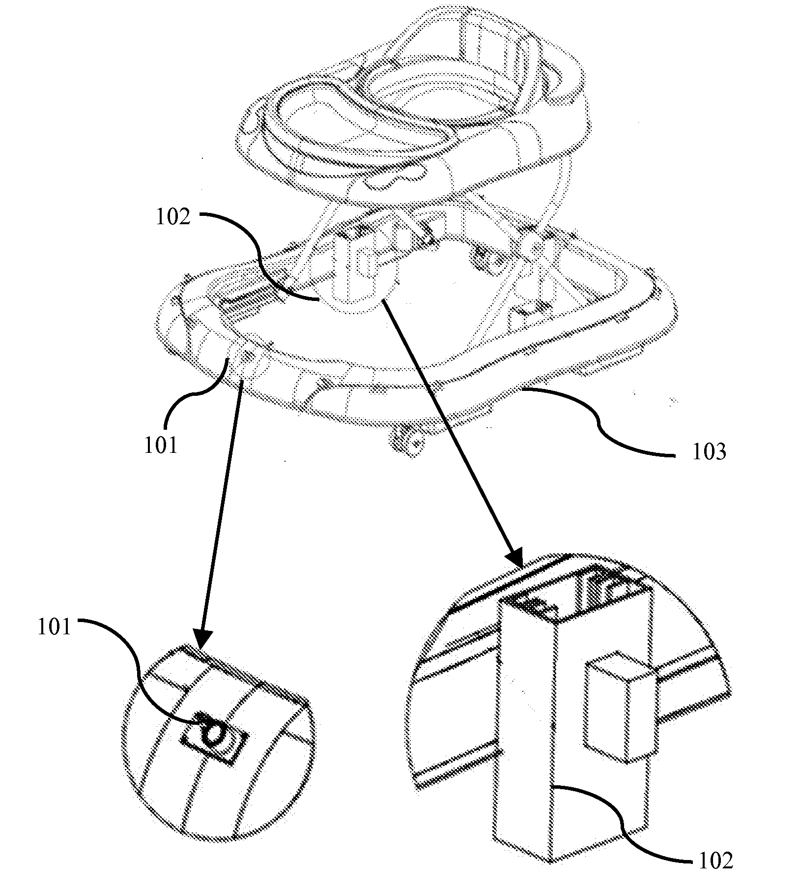
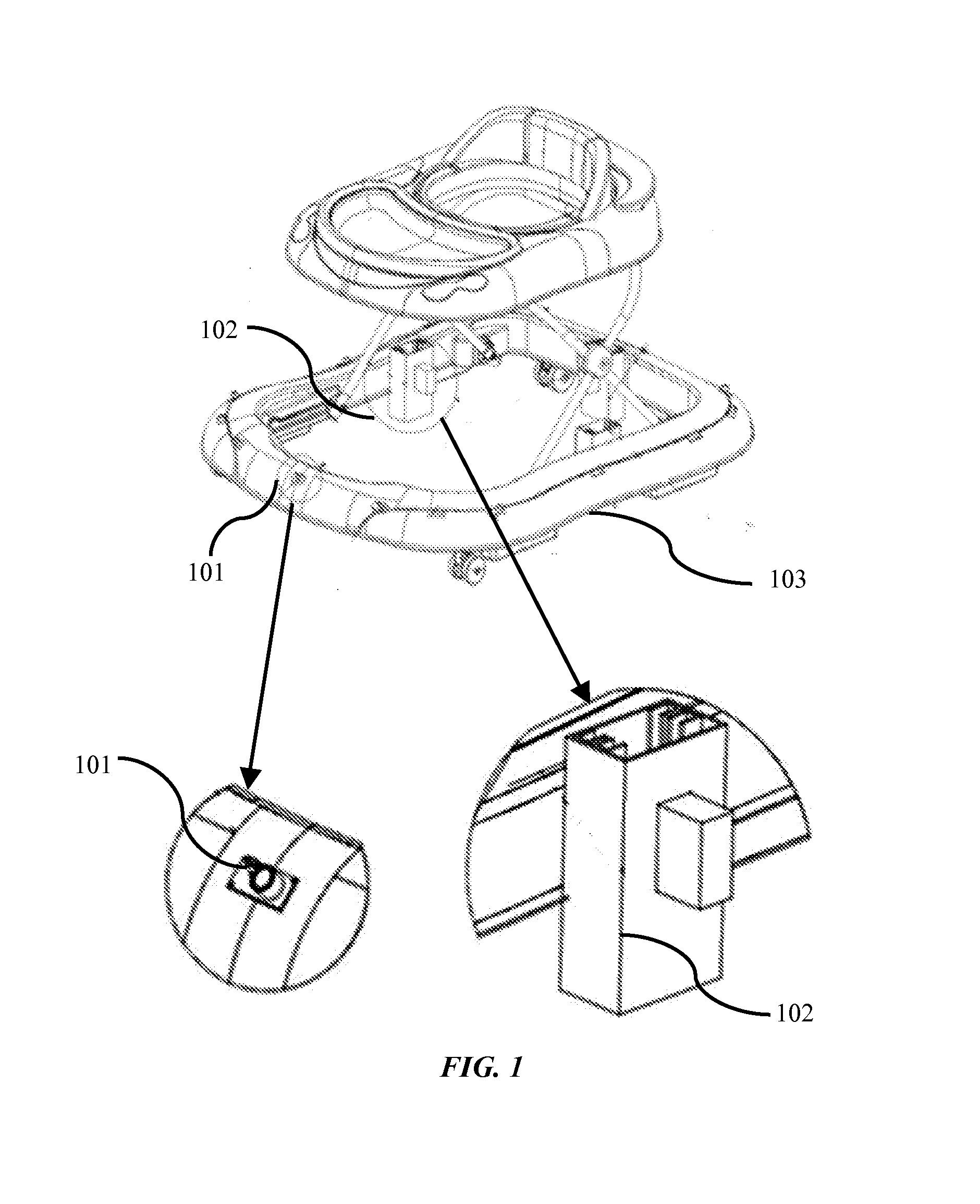
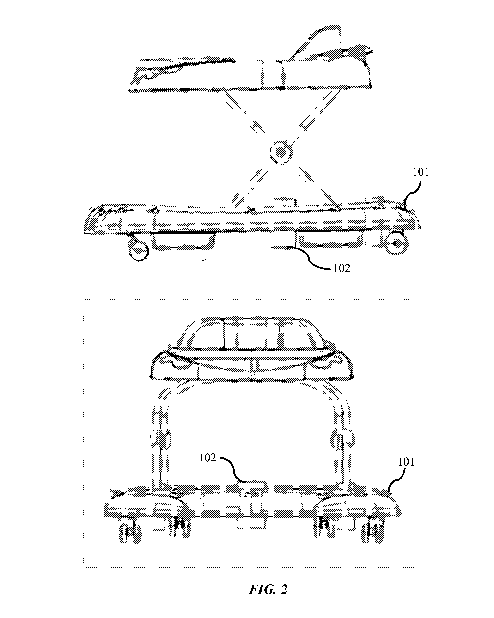
The patent describes a walker with sensors placed on the lower bumper to detect obstacles. The sensors can be of different types and can be placed in areas that are not safe for the person using the walker. The sensors can be connected to a brake blade on the walker to help with better friction and adherence to the ground surface. This invention improves the safety of the person using the walker by allowing them to detect obstacles and avoid them as best they can.

Problems solved by technology

Baby walker is one of the ordinary facilities to help a toddler to start walking The problem with a baby walker is a lack of control for the parents on the baby walker along the route the child goes and encounters the dangerous things like the heater and areas such as stairs.
The problem of collision of the walker with the obstacle occurs when the parents are not available nearby or around to monitor a baby.
The baby walkers available in the present day market do not have the option of control during an encounter with dangerous areas.
But the patent does not have any clear description about the brakes and the sensors electronic function.
Thus none of the baby walkers is provided with a baby walker to control the movement of the baby walker during the movement walker near dangerous or hazardous things like heaters, ponds, etc and areas like staircases, etc.

Method used


Image

  • Baby walker system with a braking mechanism for movement control
  • Baby walker system with a braking mechanism for movement control
  • Baby walker system with a braking mechanism for movement control

Examples


Embodiment Construction

[0009]The primary object of the embodiments herein is to provide a baby walker with a braking mechanism to control a movement of the baby walker from moving into dangerous or hazardous areas.

[0010]Another object of the embodiments herein is to provide a baby walker provided with a security mechanism for alerting the parents in tricky or dangerous situations.

[0011]Yet another object of the embodiments herein is to provide a baby walker with automatic brakes to stop the baby walker.

[0012]Yet another object of the embodiments herein is to provide a baby walker with sensors and brakes which are fitted to the existing baby walkers without any main changes to the original structure of the walker.

[0013]Yet another object of the embodiments herein is to provide a baby walker with a plurality of sensors, lasers and cameras to secure the baby walker from unpredicted dangers.

SUMMARY

[0014]The various embodiments herein provide a baby walker with braking mechanism to control a movement of the ba...


PUM


Abstract

The various embodiments herein provide a baby walker with braking mechanism to control a movement of the baby walker from moving into dangerous areas. The baby walker comprises a sensor unit, a wave transmitter system, a braking system and a power supply unit. The sensor unit is configured to sense an obstacle in the way of walker. The wave transmitter system, in communication with the sensor unit, is configured to generate signals on sensing the obstacle. The braking system, in communication with the wave transmitter, is configured to control movement of the walker upon reception of signals from the wave transmitter. The power supply unit is configured to supply electric power to the sensor unit, the wave transceiver the braking system.

Description

CROSS REFERENCETO RELATED APPLICATION[0001]The present application is a continuation in part of a non provisional application with Ser. No. 14 / 330,009 which claims the benefit and the priority of the United Sates (U.S.) Provisional Patent application with Ser. No. 61 / 846,983 filed on Jul. 16, 2013 with title, “SMART BABY WALKER WITH A BRAKE SYSTEM TO CONTROL THE BABY'S RANGE OF MOTION”, and the contents of which is incorporated in its entirety as reference herein.TECHNICAL FIELD [0002]The embodiments herein generally relates to baby walkers. The embodiments herein particularly relates to a baby walker with a safety feature. The embodiments herein more particularly relates to a baby walker with a braking mechanism to avoid an obstacle in the walker's way.DESCRIPTION OF THE RELATED ART[0003]Baby walker is one of the ordinary facilities to help a toddler to start walking The problem with a baby walker is a lack of control for the parents on the baby walker along the route the child goe...

Claims


Application Information

Patent Timeline
IPC IPC(8): A47D15/00A47D13/04
CPCA47D13/04A47D15/00A47D13/043
Inventor ASFA, AMIRMASOOD
Owner ASFA AMIRMASOOD
Learn More