Color imaging element and imaging device

a color imaging element and imaging device technology, applied in the field of color imaging elements and imaging devices, can solve the problems of poor pixel reproduction precision in a limited resolution region, ineffective for false colors in high frequency portions, and complicated demosaicing processing, so as to improve the reproduction precision of demosaicing processing, suppress aliasing, and high resolution

Active Publication Date: 2015-04-23
FUJIFILM CORP
View PDF7 Cites 4 Cited by
  • Summary
  • Abstract
  • Description
  • Claims
  • Application Information

AI Technical Summary

Benefits of technology

[0018]In view of the above circumstances, the present invention has been made, and an object of the present invention is to provide a color imaging element capable of reducing occurrence of false color and achieving high resolution and capable of simplifying the processing in a subsequent stage more than a conventional random array. In addition, another object of the present invention is to provide an imaging device using such a color imaging element.
[0023]The present invention provides an array of the color filters in which one or more first filters are placed in a filter line in each direction from the first direction to the fourth direction, and thus can improve reproduction precision of demosaicing processing in a high frequency region.
[0024]In addition, the basic array pattern is repeatedly placed in the first direction and in the second direction, and thus the array of the color filters can be processed according to a repeating pattern when a process in a subsequent stage such as demosaicing processing is performed, thereby simplifying the process in a subsequent stage more than a conventional random array.
[0025]In addition, the basic array pattern includes square patterns corresponding to 3×3 pixels composed of one of the second filter in the center and eight of the first filters surrounding eight directions of the second filter, and grating filter lines in the first direction and in the second direction, in which the first filter and the second filter are placed side by side surrounding the four directions of the square pattern. Therefore, the geometric regularity due to coupling between the square patterns and the grating filter lines causes the ratio of the number of pixels of the first color corresponding to the first filter to be greater than the ratio of each of the numbers of pixels of each color of the second colors corresponding to the second filters, and at the same time can make it easy to evenly distribute the second filters over the entire color filter array, and can facilitate signal processing in a subsequent stage, thus further improving the image reproduction precision and reliability.
[0032]It is preferable that in the basic array pattern, one or more second filters corresponding to each color of the second colors are placed in each filter line in the first direction and in the second direction in the basic array pattern. This configuration can reduce color moire (false color) which otherwise would occur by an input image having a high frequency component.
[0036]The color imaging element of the present invention can improve reproduction precision of demosaicing processing in a high frequency region and suppress aliasing. In addition, the color imaging element can achieve high resolution by reducing occurrence of color moire (false color). Further, the color imaging element can perform pixel demosaicing processing with high precision. Furthermore, the basic array pattern composed of square patterns and grating filter lines is repeated in the first direction and the second direction, and thus the color filter array can perform signal processing in a subsequent stage according to a repeating pattern of square patterns and grating filter lines, and can simplify the processing in a subsequent stage more than the conventional random array. Still furthermore, the imaging device of the present invention can reduce occurrence of false color and achieve high resolution, and can simplify the processing in a subsequent stage more than the conventional random array.

Problems solved by technology

The color imaging element described in Japanese Patent Application Laid-Open No. 2000-308080 needs to optimize each random pattern when demosaicing processing is performed in a subsequent stage since a filter array is random, thus causing a problem of complicating the demosaicing processing.
Note that the random array is effective for color moire having a low frequency, but is not effective for a false color in a high frequency portion.
In addition, the color imaging element described in Japanese Patent Application Laid-Open No. 2005-136766 has a problem of poor pixel reproduction precision in a limited resolution region (particularly in the diagonal directions), because G pixels (brightness pixels) are placed in a checkered pattern.
Meanwhile, the color imaging element described in Japanese Patent Application Laid-Open No. 8-23543 is not effective for a false color in a high frequency portion in a horizontal or vertical direction because the ratio of the number of pixels of G with respect to each of the numbers of pixels of R and B is six times higher than the ratio of the number of pixels of G in the Bayer array, and filter lines of only G pixels are located in the horizontal or vertical direction.

Method used


Image

  • Color imaging element and imaging device
  • Color imaging element and imaging device
  • Color imaging element and imaging device

Examples


first embodiment

[Color Filter Array ]

[0074]The color filter array 22 has the following features (1), (2), (3), (4), (5), (6), and (7).

[Feature (1)]

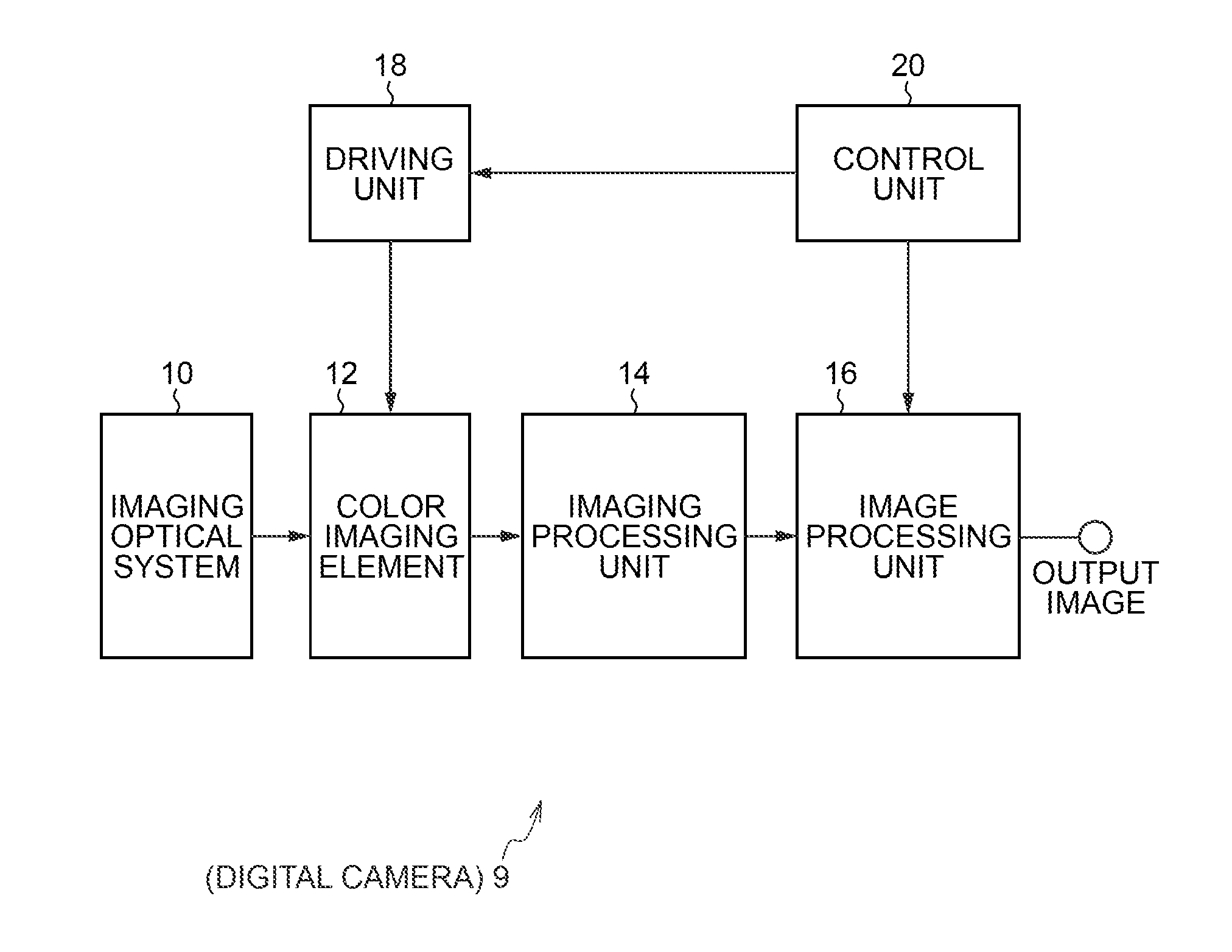
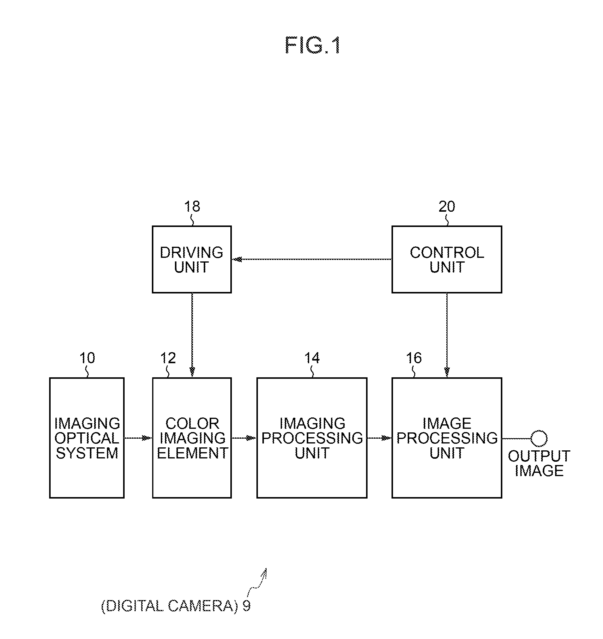
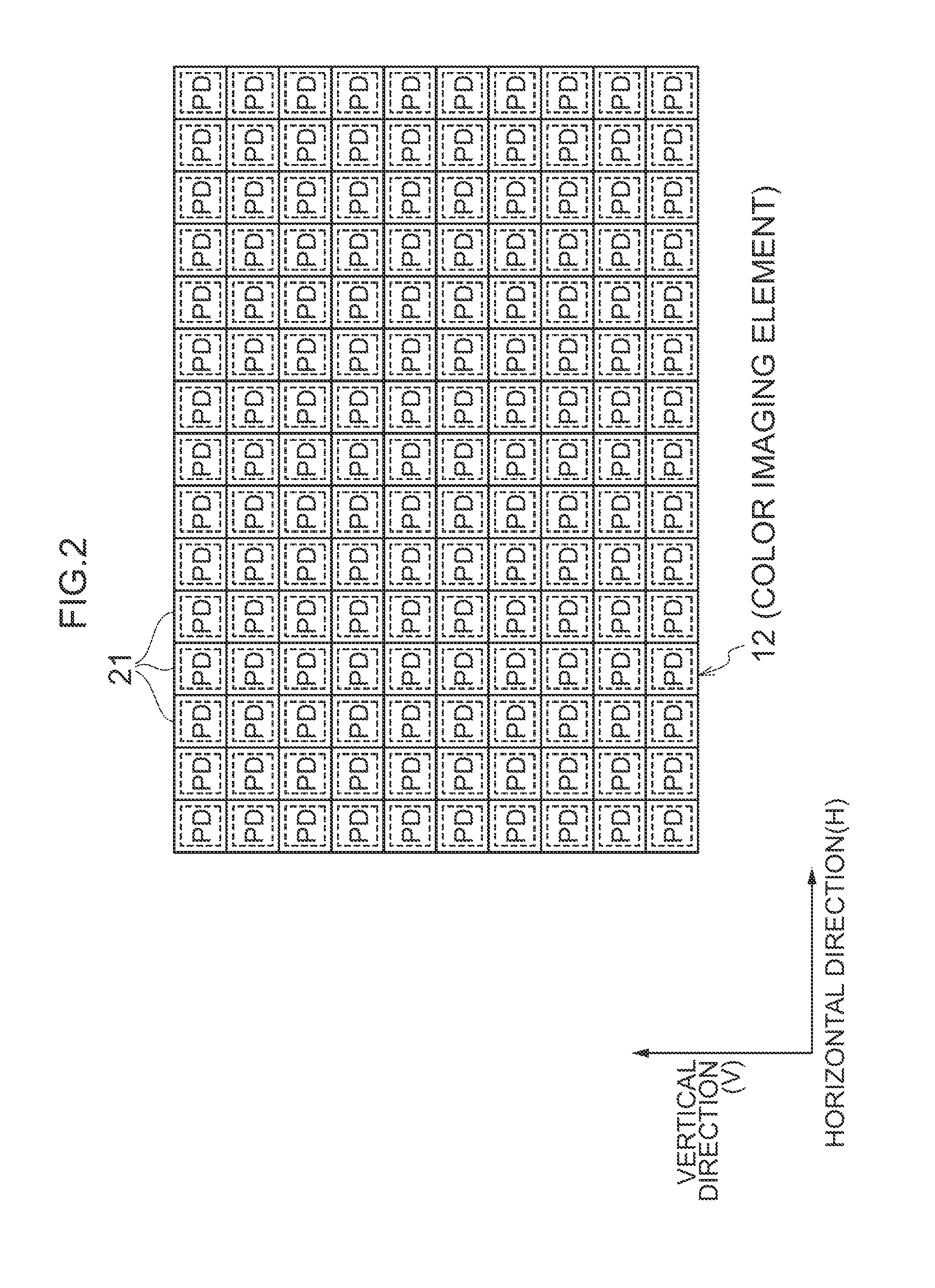
[0075]As illustrated in FIGS. 3 and 4, the color filter array 22 includes basic array patterns P1, each of which is a square array pattern corresponding to 10×10 pixels, wherein the basic array pattern P1 is repeatedly placed in the first direction H (horizontal direction) and in the second direction V (vertical direction). Specifically, in the color filter array 22, the R filter 23R, the G filter 23G, and the B filter 23B of each color are periodically disposed. For this reason, the R, G, and B signals read from the color imaging element 12 can be subjected to demosaicing processing and other processing according to a repeating pattern. As a result, the color filter array 22 can simplify processing in a subsequent stage more than the conventional random array.

[0076]In addition, when thinning processing is performed in units of the basic array patterns P...

second embodiment

[Color Imaging Element of Second Embodiment]

[0104]As illustrated in FIG. 8, a color filter array 30 of the second embodiment is formed by repeatedly arranging a basic array pattern P2 different from the basic array pattern P1 in the first direction H and in the second direction V which are orthogonal to each other. The basic array pattern P2 is basically the same as the basic array pattern P1 of the first embodiment except for the arrangement of the grating filter lines HG (25 and 26) in the first direction H and the grating filter lines VG (27 and 28) in the second direction V (except that “25” is interchanged with “26” of the grating filter lines HG in the first direction H, and “27” is interchanged with “28” of the grating filter lines VG in the second direction V). In short, what is different is the order of arranging the R filters 23R and the B filters 23B in the grating filter lines HG and VG. Thus, the color filter array 30 of the second embodiment has the similar features to...

third embodiment

[Color Imaging Element of Third Embodiment]

[0105]Next, with reference to FIG. 9, a color imaging element of the third embodiment of the present invention will be described. Note that the color imaging element of the third embodiment has basically the same configuration as the configuration of the color imaging element of the aforementioned first embodiment except for a color filter array 32 having the following feature (7-3a) instead of the aforementioned feature (7-3) and having the following feature (7-4a) instead of the aforementioned feature (7-4). For this reason, the same reference numerals or characters are assigned to the same functions and configurations as the functions and the configurations of the above-described first embodiment, and description thereof is omitted.

[Color Filter Array of Third Embodiment]

[0106]The color filter array 32 includes a basic array pattern P3 having the RGB filters 23R, 23G, and 23B arranged in an array pattern corresponding to 8×8 pixels, and ...


PUM


Abstract

The color imaging element and the imaging device according to the present invention can improve reproduction precision of demosaicing processing in a high frequency region and suppress aliasing. Further, the color imaging element can achieve high resolution by reducing occurrence of color moire (false color). Furthermore, the color imaging element and the imaging device can perform pixel demosaicing processing with high precision. Still furthermore, a basic array pattern including a square pattern and a grating filter line is repeated in a first direction and a second direction, and thus a color filter array can perform signal processing in a subsequent stage according to a repeating pattern of the square pattern and the grating filter line, and can simplify the processing in a subsequent stage more than a conventional random array.

Description

CROSS-REFERENCE TO RELATED APPLICATIONS[0001]This application is a Continuation of PCT International Application No. PCT / JP2013 / 055192 filed on Feb. 27, 2013, which claims priority under 35 U.S.C. §119(a) to Japanese Patent Application No. 2012-152675 filed on Jul. 6, 2012. Each of the above application(s) is hereby expressly incorporated by reference, in its entirety, into the present application.BACKGROUND OF THE INVENTION[0002]1. Field of the Invention[0003]The present invention relates to a color imaging element and an imaging device and, in particular, relates to a color imaging element capable of reducing occurrence of color moire and achieving high resolution, and an imaging device using such a color imaging element.[0004]2. Description of the Related Art[0005]In a single-plate color imaging element, a single color filter is provided on each pixel, and hence each pixel has color information about only a single color. For this reason, an output image of a single-plate color im...

Claims


Application Information

Patent Timeline
Patent Type & Authority Applications(United States)
IPC IPC(8): H04N9/64H04N9/30
CPCH04N9/30H04N9/646H04N23/84H04N25/134
Inventor TANAKA, SEIJIHAYASHI, KENKICHIKAWAMURA, NORIKO
Owner FUJIFILM CORP
Why Eureka
Try Eureka