Retinal movement tracking in optical coherence tomography

a technology of optical coherence tomography and retinal movement, applied in image analysis, medical science, diagnostics, etc., can solve the problems requiring more information than necessary, and requiring extra processing burdens. to achieve the effect of reducing the effect of feedback loops

Active Publication Date: 2015-04-23
CANON KK
View PDF13 Cites 20 Cited by
  • Summary
  • Abstract
  • Description
  • Claims
  • Application Information

AI Technical Summary

Benefits of technology

[0023]In consideration of the above problems, it is desired to provide an OCT apparatus that provides a high-quality, high scan-rate fundus image suitable for observation (or “preview”) without sacrificing OCT scan rate in the correction of eye movement artifacts in tomographic images. It is also desired to reduce the effects of feedback loops caused by alignment measurements being performed after acquisition of OCT scan data.

Problems solved by technology

One problem with this known apparatus is that much more information has to be processed than necessary because every single b-scan has more a-scans than will be used to form a tomographic image.
This causes an extra processing burden and slows down processing.
Another problem with some known apparatuses is that synchronisation between the fundus image and the b-scan of the OCT has to be constantly monitored, and this increases processing burden as well as increasing the time taken to create a tomographic image if no scanning is performed during the synchronisation process or if b-scans have to be corrected if an asynchronicity is found.
Any kind of fundus tracking has a problem of a “feedback” delay in the feedback loop that occurs between the fundus tracking and the OCT correcting for misalignments found during the tracking.

Method used


Image

  • Retinal movement tracking in optical coherence tomography
  • Retinal movement tracking in optical coherence tomography
  • Retinal movement tracking in optical coherence tomography

Examples


Embodiment Construction

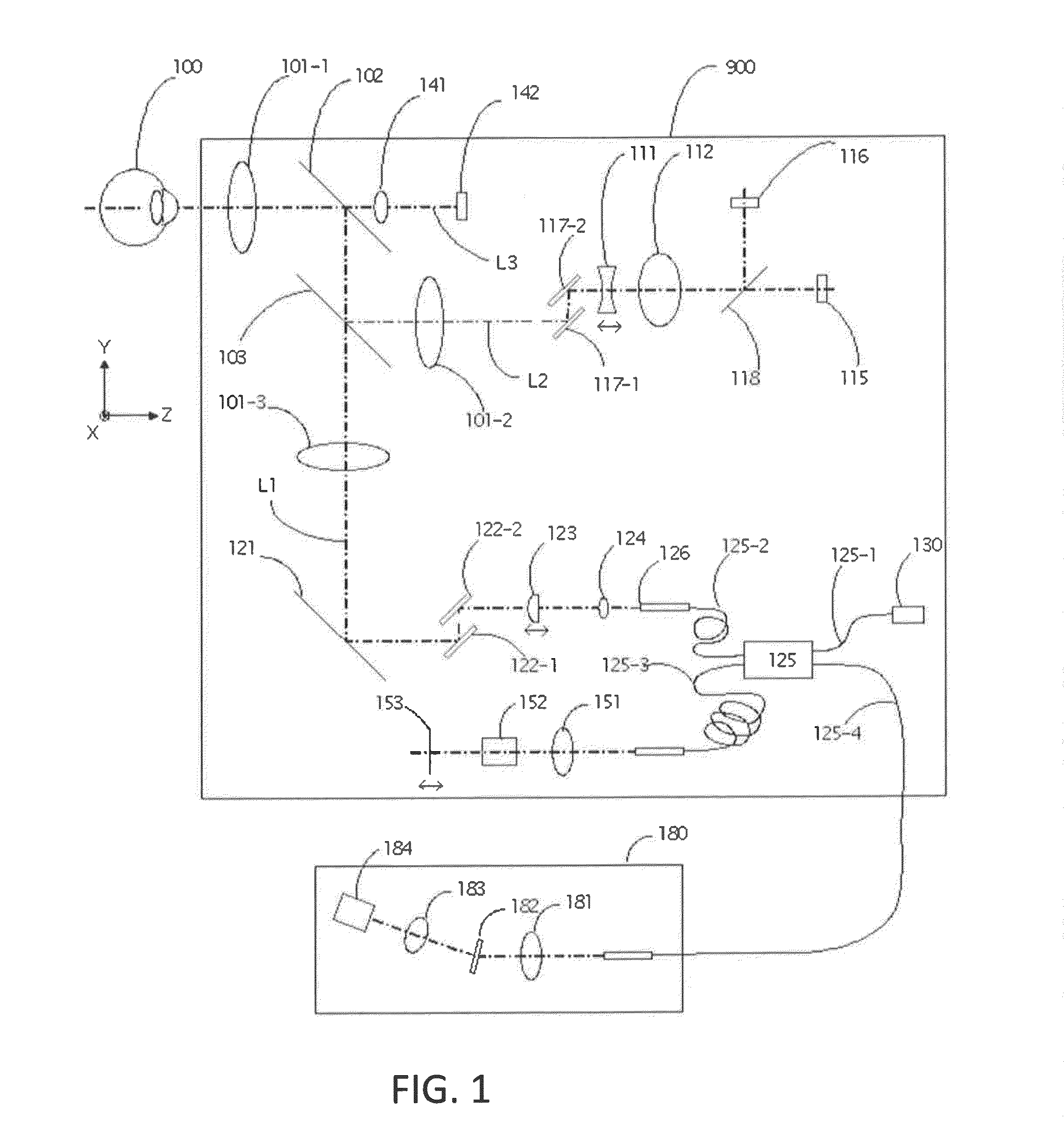
[0035]The arrangement of an optical coherence tomographic apparatus (OCT apparatus) will be described with reference to FIG. 1. The optical coherence tomographic apparatus includes an optical head 900 and a spectrometer 180. The optical coherence tomographic apparatus obtains a tomographic image of an object to be examined based on the light obtained by combining return (i.e. reflected, but also some scattered) light from the object that has been irradiated with measurement light with reference light corresponding to the measurement light.

[0036]The internal arrangement of the optical head 900 will be described first. The optical head 900 comprises a measurement optical system for capturing an anterior eye image of an eye 100 to be examined as well as a two-dimensional image and a tomographic image of the fundus. An objective lens 101-1 is disposed to face the eye 100. On the optical axis of this lens, a first dichroic mirror 102 and a second dichroic mirror 103 serve as optical path...


PUM


Abstract

The present invention defines a method of correcting for eye movement during optical coherence tomography imaging. The method includes imaging (by scanning) a fundus of an eye to obtain a fundus image (for example, using an SLO); scanning the fundus to obtain a plurality of tomographic images (for example, using OCT); determining, at predetermined intervals, an alignment of the tomographic images with respect to the fundus image, and, if it is determined that there is a misalignment, determining the number of tomographic images that have been scanned in the predetermined interval since the previous alignment determination; determining the offset by which the tomographic images are misaligned; applying the offset to the next tomographic image to be scanned and rescanning the determined number of tomographic images that were scanned during the interval between misalignment being determined and offset being applied.

Description

[0001]This application claims the benefit under 35 U.S.C. §119(a)-(d) of United Kingdom Patent Application No. 13189854.6, filed on Oct. 23, 2013 and entitled “RETINAL MOVEMENT TRACKING IN OPTICAL COHERENCE TOMOGRAPHY.” The above cited patent application is incorporated herein by reference in its entirety.TECHNICAL FIELD[0002]The present invention relates to the imaging of a fundus oculi using in particular optical coherence tomography (OCT). More specifically, the present invention relates to the correction of OCT images when the fundus oculi moves during imaging.BACKGROUND ART[0003]Optical coherence tomography (OCT), though used in many medical and biological fields for medical imaging, is particularly suited to ophthalmic imaging because it is non-invasive and can be performed even through the anterior structures of the eye to obtain a 3-D image of the fundus oculi (i.e. the retina of the eye).[0004]Various ophthalmic apparatuses that use optical apparatuses are known in the art,...

Claims


Application Information

Patent Timeline
Patent Type & Authority Applications(United States)
IPC IPC(8): A61B3/10A61B3/113A61B3/12
CPCA61B3/102A61B3/113A61B3/1225A61B3/1233A61B3/10G06T7/74G06T7/246G06T7/337A61B3/0025G06T7/0016G06T2207/10101G06T2207/30041
Inventor ORLOWSKI, SLAWOMIRDZIUBAK, TOMASZSZATKOWSKI, JAKUBDALASINSKI, PAWELPANKOWIEC, MACIEJ
Owner CANON KK
Why Eureka
Try Eureka