Microelectromechanical gyroscope with compensation of quadrature error drift

a microelectromechanical and gyroscope technology, applied in the direction of acceleration measurement using interia forces, turn-sensitive devices, instruments, etc., can solve the problems of quadrature errors, non-complete solution of problems, and virtually unavoidable disturbance sources of manufacturing defects and process spreads

Active Publication Date: 2015-04-30
STMICROELECTRONICS INT NV
View PDF13 Cites 40 Cited by
  • Summary
  • Abstract
  • Description
  • Claims
  • Application Information

AI Technical Summary

Problems solved by technology

However, the MEMS gyroscope has a complex structure and electromechanical interactions between the movable masses and supporting body are often non-linear, the useful signal components are mixed with spurious components, that do not contribute to measurement of the angular speed.
For example, manufacturing defects and process spreads are virtually unavoidable sources of disturbance, the effect of which is not predictable.
A common defect depends on the fact that the direction of oscillation of the driving mass is not perfectly coincident with the intended design degree of freedom.
Such a defect is normally due to imperfections in the elastic connec

Method used


Image

  • Microelectromechanical gyroscope with compensation of quadrature error drift
  • Microelectromechanical gyroscope with compensation of quadrature error drift
  • Microelectromechanical gyroscope with compensation of quadrature error drift

Examples


Embodiment Construction

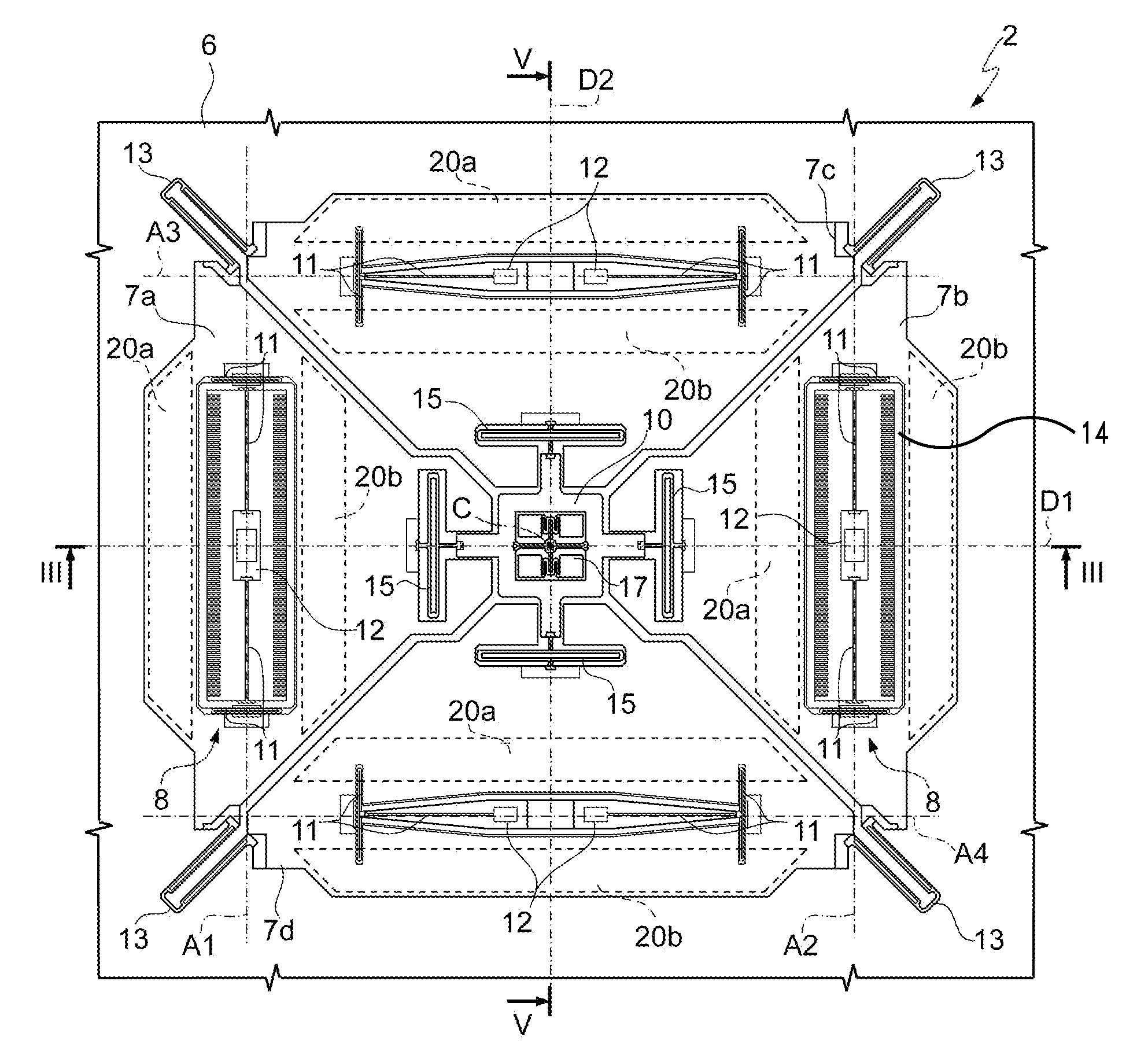
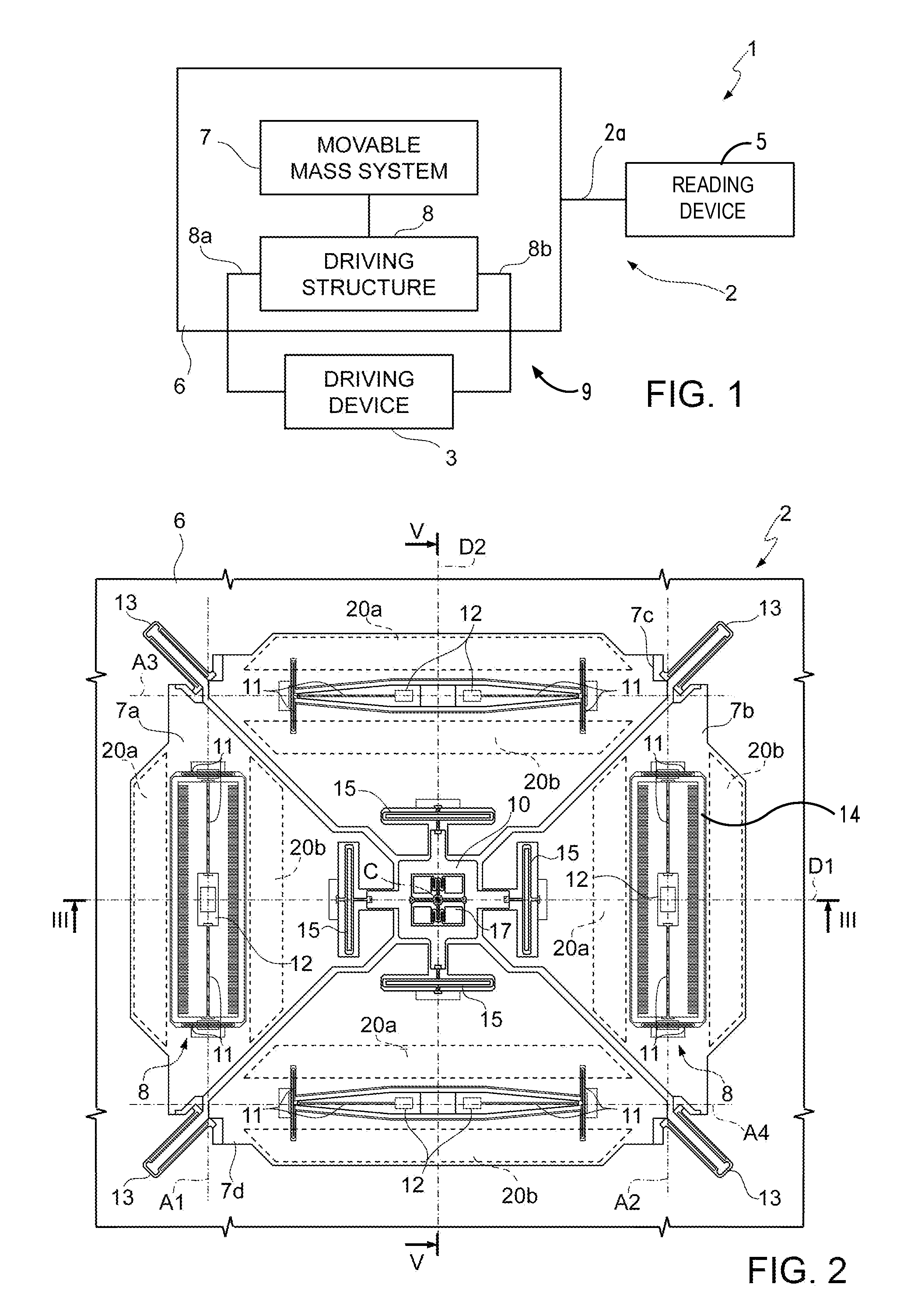
[0030]FIG. 1 shows as a whole a microelectromechanical gyroscope 1, which comprises a microstructure 2, made of semiconductor material, a driving device 3 and a reading device 5.

[0031]The microstructure 2 is made of semiconductor material and comprises a supporting body 6, a system of movable masses 7 and a driving structure 8.

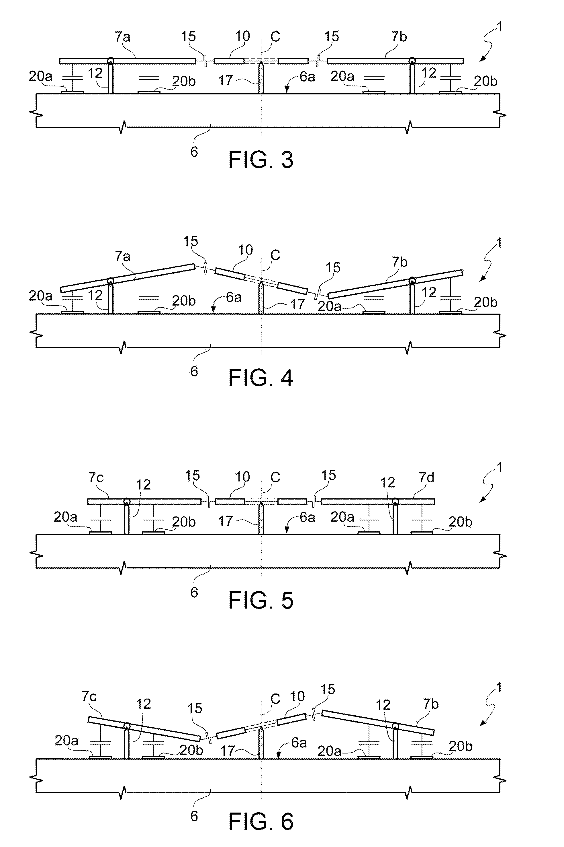
[0032]The movable masses 7 are mechanically coupled to the supporting body 6 through elastic connections (here not shown) so that a first and a second respective relative degree of freedom are set between each one of the movable masses 7 and the supporting body 6. As discussed in greater detail later on, each one of the movable masses 7 has a translational degree of freedom, along a respective driving axis, and a rotary degree of freedom, which allows the movable mass to tilt about a respective sensing axis in response to rotations of the supporting body 6.

[0033]The driving structure 8 has driving terminals 8a and is configured to provide electrostatic driving...


PUM


Abstract

A microelectromechanical gyroscope, includes: a supporting body; a first movable mass and a second movable mass, which are oscillatable according to a first driving axis and tiltable about respective a first and second sensing axes and are symmetrically arranged with respect to a center of symmetry; first sensing electrodes and a second sensing electrodes associated with the first and second movable masses and arranged on the supporting body symmetrically with respect to the first and second sensing axis, the first and second movable masses being capacitively coupled to the respective first sensing electrode and to the respective second sensing electrode, a bridge element elastically coupled to respective inner ends of the first movable mass and of the second movable mass and coupled to the supporting body so as to be tiltable about an axis transverse to the first driving axis.

Description

BACKGROUND[0001]1. Technical Field[0002]The present disclosure relates to a microelectromechanical gyroscope with compensation of quadrature error drift.[0003]2. Description of the Related Art[0004]As is known, use of microelectromechanical systems is becoming more and more widespread in several fields of technology and has lent encouraging results, especially in manufacturing of inertial sensors, microintegrated gyroscopes and electromechanical oscillators for various applications.[0005]MEMS of this type are generally based on microelectromechanical structures comprising a supporting body and at least on movable mass, coupled to the supporting body through flexures. Flexures are configured to allow the movable mass to oscillate with respect to the supporting body in accordance with one or more degrees of freedom. The movable mass is capacitively coupled to a plurality of static electrodes on the supporting body, thus forming capacitors with variable capacitance. The movement of the...

Claims


Application Information

Patent Timeline
IPC IPC(8): G01C19/5712
CPCG01C19/5712G01C19/5747G01C19/56G01C19/5719G01C19/574
Inventor VALZASINA, CARLOFALORNI, LUCA GIUSEPPE
Owner STMICROELECTRONICS INT NV
Why Eureka
Try Eureka