Aspirator motive flow control for vacuum generation and compressor bypass

a technology of compressor bypass and air flow control, which is applied in the direction of machines/engines, liquid fuel feeders, combustion air/fuel air treatment, etc., can solve the problems of compressor degradation, performance problems, and incorporation of such valves, and achieve the effect of expanding the operating region of the engin

Active Publication Date: 2015-04-30
FORD GLOBAL TECH LLC
View PDF0 Cites 39 Cited by
  • Summary
  • Abstract
  • Description
  • Claims
  • Application Information

AI Technical Summary

Benefits of technology

[0002]Turbocharging an engine allows the engine to provide power similar to that of a larger displacement engine. Thus, turbocharging can extend the operating region of an engine.

Problems solved by technology

Under certain conditions, the flow rate and pressure ratio across the compressor can fluctuate to levels that may result in noise disturbances, and in more severe cases, performance issues and compressor degradation.
However, incorporation of such valves can add significant component and operating costs to engine systems.
However, again, adding valves to engine systems which already include various valves serving other purposes (such as CBVs) can add significant component and operating costs.

Method used


Image

  • Aspirator motive flow control for vacuum generation and compressor bypass
  • Aspirator motive flow control for vacuum generation and compressor bypass
  • Aspirator motive flow control for vacuum generation and compressor bypass

Examples


Embodiment Construction

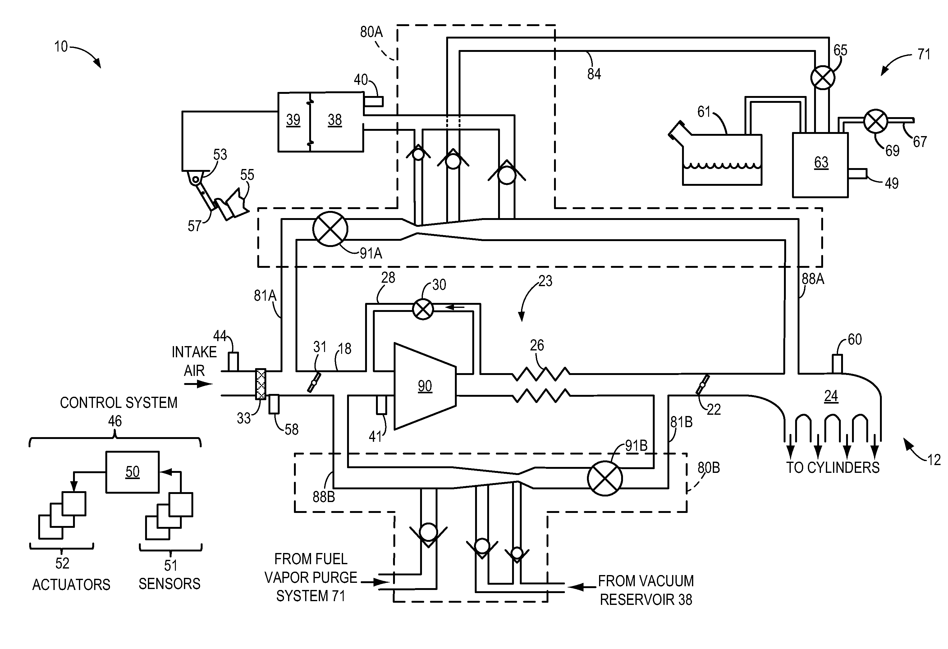
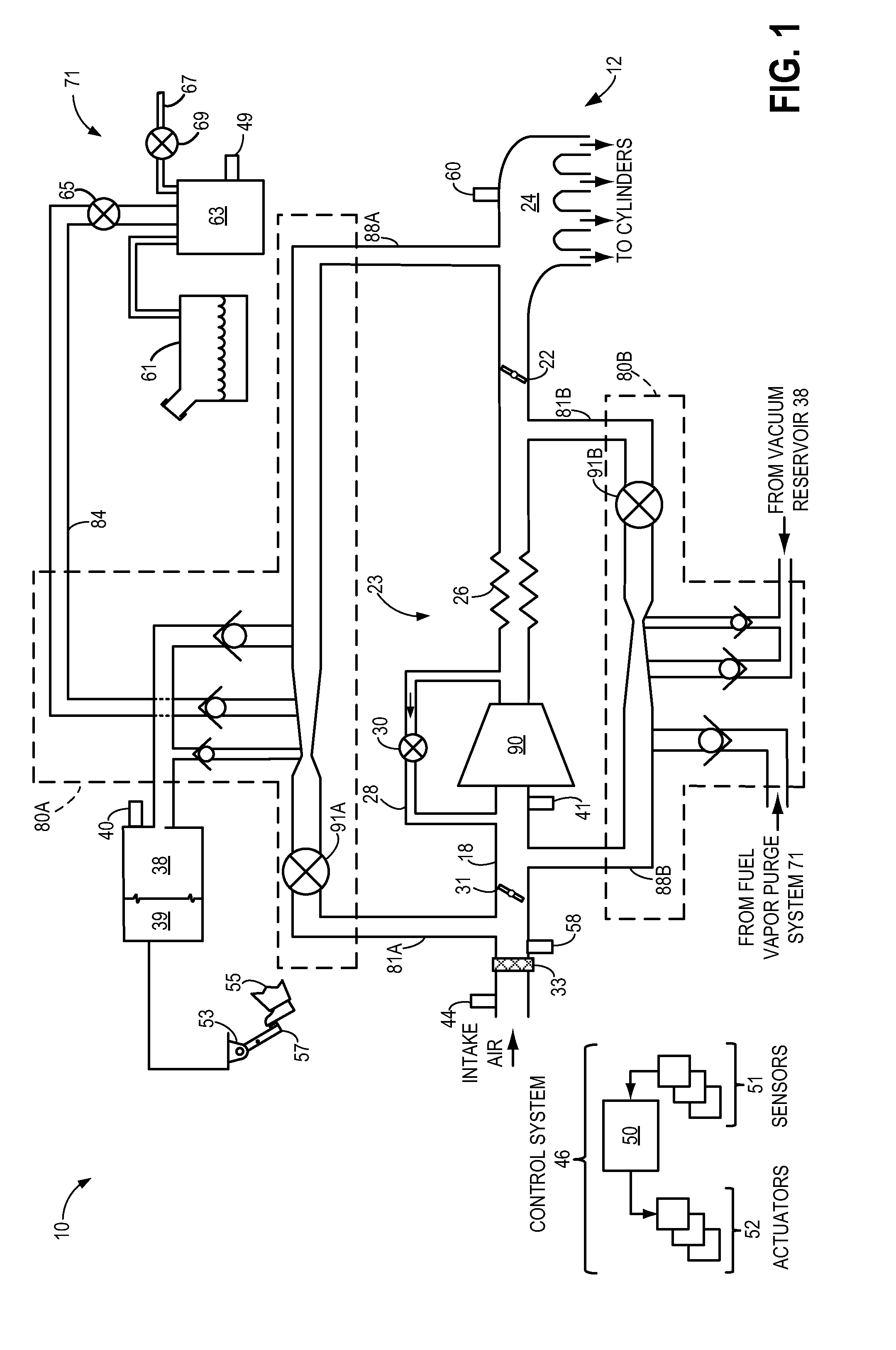
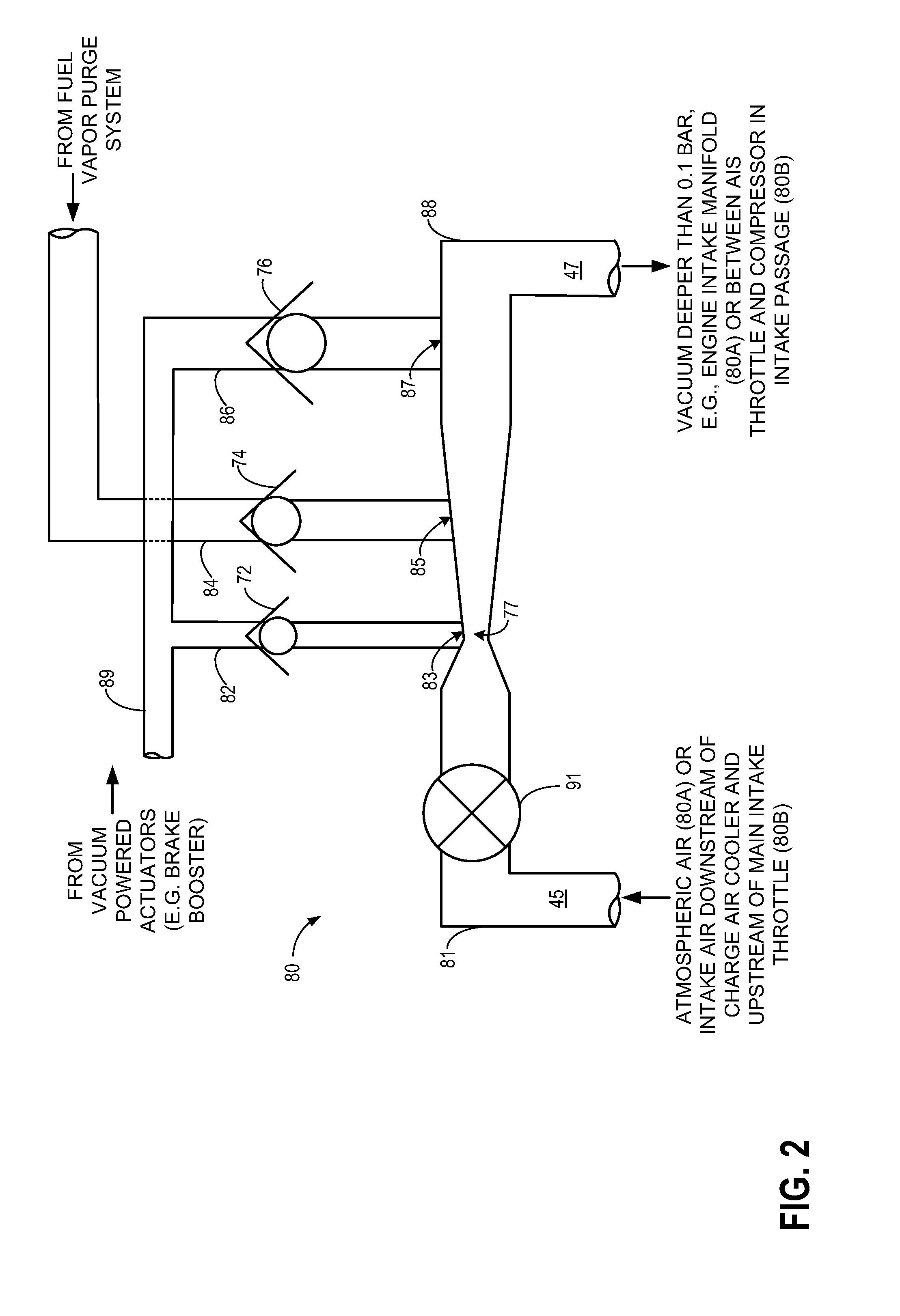
[0019]A first multiple tap aspirator with a motive inlet coupled upstream of a compressor and a mixed flow outlet coupled downstream of a throttle may generate vacuum during non-boost conditions, and may provide compressor bypass flow during compressor bypass flow while continuing to generate some vacuum. Similarly, a second multiple tap aspirator with a motive inlet coupled downstream of a compressor and a mixed flow outlet coupled upstream of a compressor may generate vacuum during boost conditions while also providing a path for compressor bypass flow. One or more suction taps of each of the aspirators may be coupled with a fuel vapor purge system, while the remaining suction taps may be coupled with a vacuum reservoir, as in the engine system of FIG. 1. Alternatively, all suction taps of the aspirators may be coupled with a vacuum reservoir, as in the engine system of FIG. 3. Detail views of example multiple tap aspirators are provided in FIGS. 2 and 4. As shown, check valves ma...


PUM


Abstract

Systems and methods are provided for engine systems including a first multiple tap aspirator with a motive inlet coupled to an intake upstream of an air induction system throttle and a mixed flow outlet coupled to an intake manifold, and a second multiple tap aspirator with a motive inlet coupled to the intake upstream of a main throttle and a mixed flow outlet coupled to the intake downstream of the air induction system throttle. During non-boost conditions, intake air may be selectably diverted around a compressor and through the first and/or second aspirator based on desired vacuum generation. During boost conditions, the first and second aspirators may function as compressor bypass valves, and intake air may be selectably directed from downstream of the compressor to upstream of the compressor via the first and/or second aspirator based on a desired compressor bypass flow.

Description

FIELD[0001]The present invention relates to an engine system including aspirators providing both vacuum generation and boost / surge control.BACKGROUND AND SUMMARY[0002]Turbocharging an engine allows the engine to provide power similar to that of a larger displacement engine. Thus, turbocharging can extend the operating region of an engine.[0003]Turbochargers function by compressing intake air in a compressor via a turbine operated by exhaust gas flow. Under certain conditions, the flow rate and pressure ratio across the compressor can fluctuate to levels that may result in noise disturbances, and in more severe cases, performance issues and compressor degradation. Such compressor surge may be mitigated by one or more compressor bypass valves (CBVs). The CBVs may recirculate compressed air from the compressor outlet to the compressor inlet, and thus may be arranged in a passage which is coupled to the intake upstream of the compressor and downstream of the compressor in some examples....

Claims


Application Information

Patent Timeline
Patent Type & Authority Applications(United States)
IPC IPC(8): F02M35/10
CPCF02M35/10229F02M35/10019F02M35/10157F02M35/10255F02B33/44F02M25/089F02M35/10118F02M35/10163F02M35/10222Y02T10/12
Inventor PURSIFULL, ROSS DYKSTRA
Owner FORD GLOBAL TECH LLC
Why Eureka
Try Eureka