Method and system for coating a pipe

a technology of pipeline and coating, applied in the direction of hollow article cleaning, mechanical equipment, instruments, etc., can solve the problems of pipeline deterioration, pipeline deterioration, holes, cracks, etc., and achieve the effect of effectively sealing all cracks and faults, reducing time, and being inexpensive to carry ou

Active Publication Date: 2015-04-30
WARREN ENVIRONMENTAL & COATING LLC
View PDF14 Cites 16 Cited by
  • Summary
  • Abstract
  • Description
  • Claims
  • Application Information

AI Technical Summary

Benefits of technology

[0016]This invention operates in a smart manner to reduce the time required to evaluate and repair a pipeline. Further the system applies only the amount of material needed to repair the existing condition of the pipe in real time.
[0017]Therefore, it is an object of the present invention to provide a new and novel system and process for lining the interior surface of a pipeline to repair and salvage the pipe so that is can be used normally in a leak-free condition. It is another object of the invention to provide a structural lining process that effectively seals all cracks and faults in an existing pipeline. A further object of the invention is to provide a lining process that evaluates the condition of the pipe and used that data to apply the required coating thickness to effect a repair that is relatively inexpensive to carry out compared to prior art processes without sacrificing the integrity of the sealing and repair accomplished by the process of the present invention.

Problems solved by technology

Since these pipelines are installed underground, they are constantly subjected to numerous environmental pressured that cause the pipeline to deteriorate.
For example, the pipeline may deteriorate due to ordinary aging, corrosive action of the fluids being transported in the line, environmental conditions such as groundwater exposure, or other reasons.
Over time, all of the wear factors that impact on the pipeline result in holes, cracks, structural breakdown and other defects in the line that must be repaired in order to prevent fluid leakage and pipeline collapse problems.
In some instances, the concern is that foreign matter, which is initially part of the actual construction of the pipeline, may begin to flake off of the interior surfaces of the damaged pipeline and enter the fluid flow within the pipeline.
For example, ductile iron piping has a clay liner surface that upon failure may allow rust to enter the fluid flow.
Finally, the potential exists for the introduction of substances that flow from the surrounding underground environment into the pipeline or for the water that is being carried through the pipeline conduit to flow outwardly through the cracks leading to a loss of water pressure and other problems.
Further, the wall materials of the pipeline itself may breakdown and deteriorate from the outside in.
As the materials breakdown, corrode or otherwise wear the strength of the wall itself is compromised.
Should the walls deteriorate significantly, the pipeline is at risk of failure.
Given the millions of miles of installed pipeline in the United States alone, this solution would be prohibitively expensive.
Further, such pipelines are typically located beneath streets and right of ways where digging would create traffic flow problems and require extensive repaving of roadways as the replacement process was completed.
Although the above-described conventional methods may be somewhat effective in repairing pipelines, they still suffer from various problems.
For example, problems arise concerning the inversion of a felt liner because it is relatively delicate and tends to break or rip during the inversion process.
Also, pulling prior art liner tubes around corners is very difficult resulting in fractures in the sealing at such joints.
Also, the pipeline joints found at corners and periodically along the length of the pipeline forms voids that cannot be completely filled by the prior art methods.
Thus, the prior art methods can do nothing to improve the strength of the pipeline at its joints.
Another difficulty is that once a liner has been installed, the identification of lateral supply pipe branches are difficult to identify and clear.
Further, none of the methods above provide for a real-time analysis of the condition of the pipeline.
While these systems place a liner in the pile, they do not make a determination relating to the interior surface condition or structural wall condition of the pipeline.
As a result the lining process simply takes a one size fits all approach that may not actually address the issues with the pipeline.
Further, the approach may result in too much or too little material being added to the pipeline relative to the pipeline condition.

Method used


Image

  • Method and system for coating a pipe
  • Method and system for coating a pipe
  • Method and system for coating a pipe

Examples


Embodiment Construction

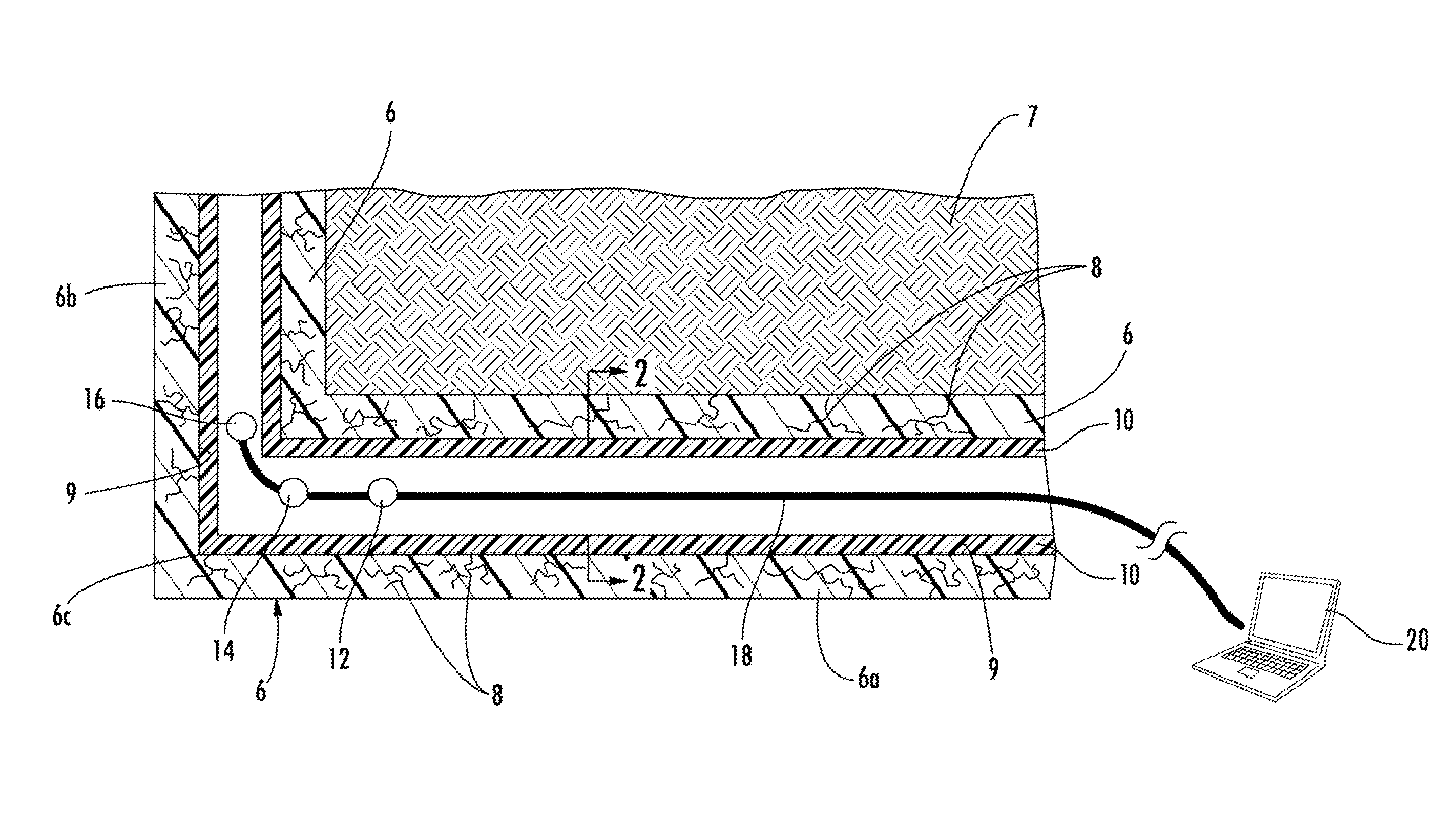
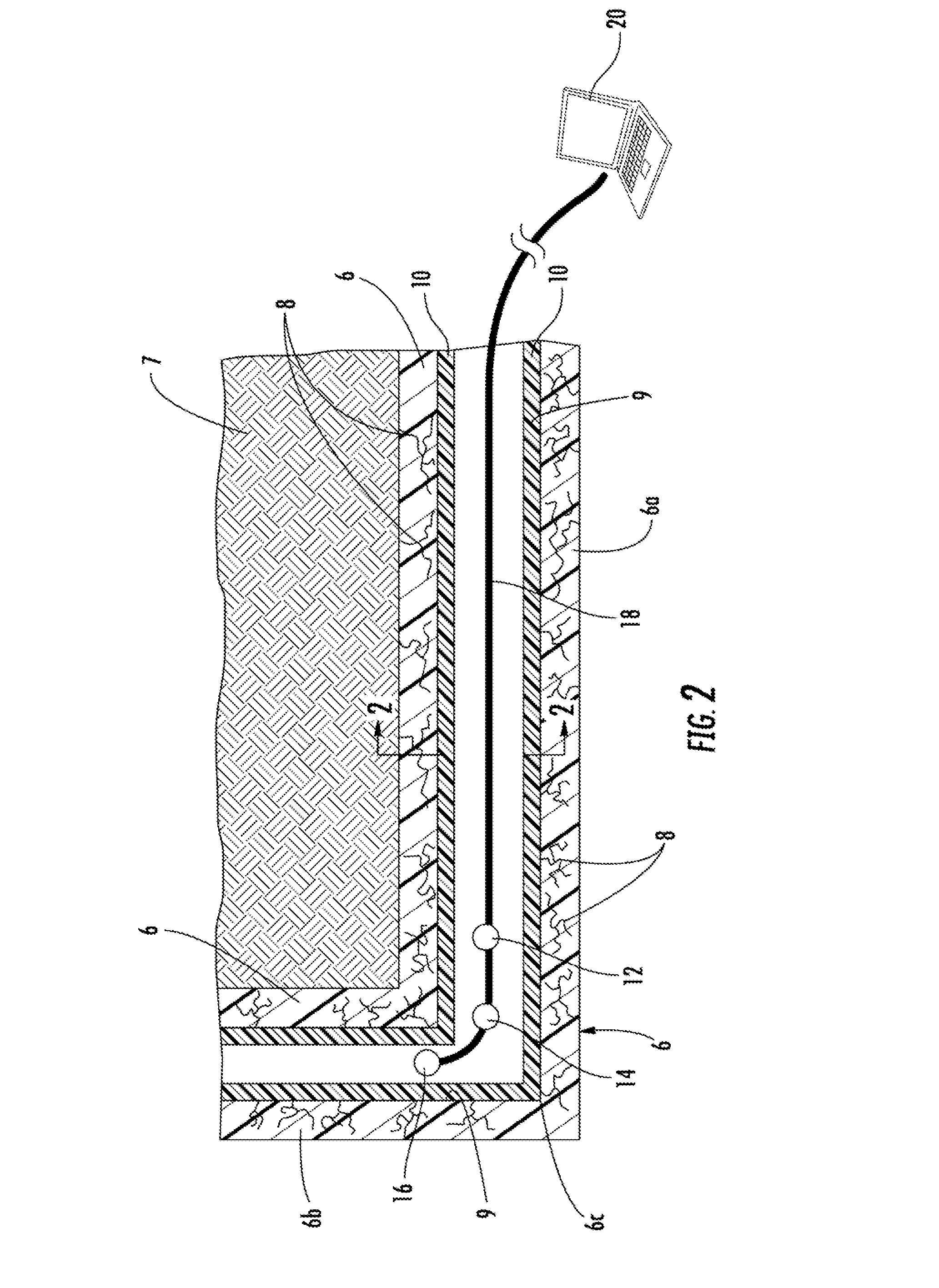
[0022]Now referring to the drawings, the method and system for repairing a pipeline in accordance with the teachings of the present invention is shown and generally illustrated in the figures. In summary, the system of the present invention is used to simultaneously inspect and repair a damaged underground pipeline, such as a water line, so that it can used in the normal course without undesirable leaks. As can be understood, cracks and leaks in a fluid line are undesirable to the associated pressure drops and flow inefficiencies. Further, in a cracked pipeline, particles commonly break off from the inner surface of the pipeline thereby contaminating the fluid that flows through the pipeline.

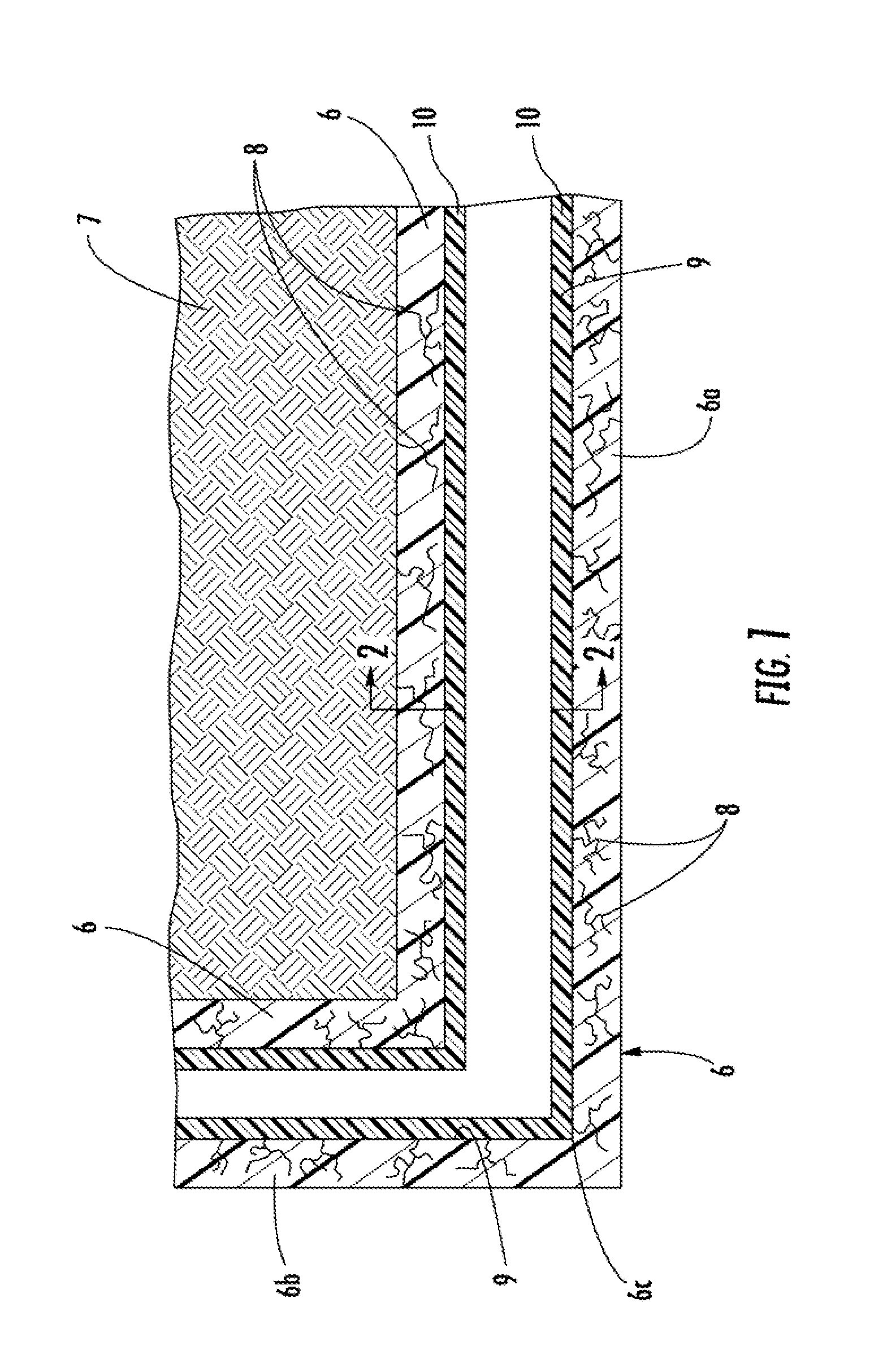
[0023]Referring first to FIG. 1, a side cross-section view of a typical pipeline installation is shown. The pipeline or host pipe 6 is installed in the ground 7 where a number of cracks 8 exist representing undesirable leaks. The pipeline 6 includes a horizontal section 6a and a vertical section...


PUM


Abstract

A method and system for evaluating the interior surface and exterior wall conditions of a pipeline while also dynamically installing a repair coating in a pipeline, such as an underground water pipeline. The system is towed into the pipeline and drawn back therethrough. As the system is drawn back, one module in the system evaluates the surface condition of the interior of the pipe and another module evaluates the structural condition of the wall of the pipe. Based on the evaluation data obtained from the two modules an epoxy material is applied to the interior surface of the pipe using a spin cast machine that is drawn behind the two modules. Preferably, a layer of epoxy is applied to the interior surface of the host pipe to the appropriate thickness based on the pipe condition as determined by the two modules.

Description

BACKGROUND OF THE INVENTION[0001]The present invention relates generally to a method and system for evaluating and repairing a distressed pipeline by installing a coating on the inside of the pipeline. More specifically, the present invention relates to system and method wherein a device is drawn along a pipeline to simultaneously assess the interior surface of the pipeline, assess the structural condition of the pipeline wall and apply a curable resin system to coat the interior of the pipeline.[0002]Throughout developed parts of the world, there are numerous pipeline conduits that run underground in order to provide utility services to businesses and residences. These utilities include water lines, sewer pipes, storm water drains, and the like. Since these pipelines are installed underground, they are constantly subjected to numerous environmental pressured that cause the pipeline to deteriorate. For example, the pipeline may deteriorate due to ordinary aging, corrosive action of ...

Claims


Application Information

Patent Timeline
Patent Type & Authority Applications(United States)
IPC IPC(8): F16L55/162
CPCF16L55/162F16L55/1645B08B9/0321B08B9/0328F16L55/18F16L2101/16F16L2101/30G01M5/0025G01M5/0033G01M5/0066G01M5/0075
Inventor WARREN, DANNY
Owner WARREN ENVIRONMENTAL & COATING LLC
Why Eureka
Try Eureka