
Downhole Pressure/Thermal Perturbation Scanning Using High Resolution Distributed Temperature Sensing

a distributed temperature sensing and pressure scanning technology, applied in the field of wellbore scanning, can solve the problems of limited ability of dts systems to detect temperature changes and damage to downhole equipmen

Inactive Publication Date: 2015-04-30
BAKER HUGHES INC
View PDF11 Cites 9 Cited by
  • Summary
  • Abstract
  • Description
  • Claims
  • Application Information

AI Technical Summary

Benefits of technology

The present patent discloses a method, system, and computer-readable media for determining features in a wellbore through inducing a thermal perturbation and measuring the temperature change along the wellbore using a distributed temperature sensing system. The technical effect is the ability to accurately and non-destructively determine features in a wellbore, such as leaks or cracks, without the need for expensive and time-consuming drilling or exploring techniques.

Problems solved by technology

Currently, the ability of DTS systems to detect temperature changes is limited by the temperature sensitivity of the DTS sensor, which is on the order of 1 to 2 degrees Celsius.
Such temperature perturbations may produce stress on the downhole system which may be damaging to the downhole equipment.

Method used


Image

  • Downhole Pressure/Thermal Perturbation Scanning Using High Resolution Distributed Temperature Sensing
  • Downhole Pressure/Thermal Perturbation Scanning Using High Resolution Distributed Temperature Sensing
  • Downhole Pressure/Thermal Perturbation Scanning Using High Resolution Distributed Temperature Sensing

Examples


Embodiment Construction

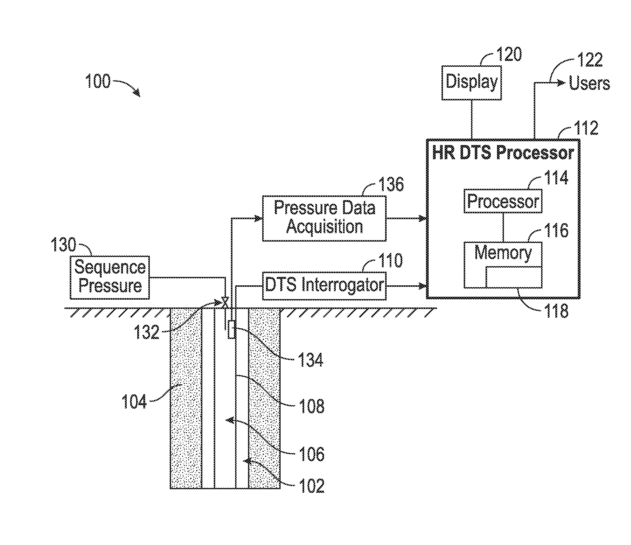
[0017]FIG. 1 shows a suitable system 100 for determining a feature in a wellbore 102 using the methods disclosed herein. The wellbore 102 is formed in a formation 104. A member such as a production tubing 106 may be disposed within the wellbore 102. In alternate embodiments, the member may include a drill string, a completion string, or other tubular string. The wellbore system 100 further includes a distributed temperature sensing (DTS) system that is used to obtain a temperature profile along the wellbore 102 over a selected time interval. The DTS system may include a fiber optic cable 108 that extends downhole, generally from a surface location, a Distributed Temperature Sensing interrogator (DTS interrogator) 110 and a High-Resolution Distributed Temperature Sensing processor (HR DTS processor) 112. In one embodiment, fiber optic cable 108 is disposed in the wellbore 102, generally alongside member 106. The fiber optic cable 108 may be either permanently deployed in the wellbore...


PUM


Abstract

A system, method and computer readable medium for determining a feature in a wellbore is disclosed. A distributed temperature sensing system is disposed along the wellbore. A thermal perturbation is induced along the wellbore. A profile is determined of temperature change in response to the applied thermal perturbation using the distributed temperature sensing system. The feature of the wellbore is determined using the measured temperature profile.

Description

CROSS REFERENCE TO RELATED APPLICATIONS[0001]The present application is a continuation-in-part of U.S. patent application Ser. No. 14 / 062,547, filed Oct. 24, 2013 and U.S. patent application Ser. No. 14 / 062,561, filed Oct. 24, 2013, the contents of which are incorporated herein by reference in their entirety.BACKGROUND OF THE DISCLOSURE[0002]1. Field of the Disclosure[0003]The present application relates to wellbore scanning and, in particular, to methods for determining features in a wellbore using a distributed temperature sensing system.[0004]2. Description of the Related Art[0005]Down-hole distributed temperature sensing (DTS) systems may be used to provide a distributed temperature survey along a wellbore. In various applications, DTS has been used to monitor thermal transitions induced by well operations or geological events, or to provide thermal information related to a geology of a formation. Different features of the formation may have different heat conductivities. Theref...

Claims


Application Information

Patent Timeline
Patent Type & Authority Applications(United States)
IPC IPC(8): G01V9/00E21B36/00E21B47/04
CPCG01V9/005E21B36/00E21B47/04E21B47/09E21B47/07E21B47/103E21B47/0025
Inventor CHEN, JEFFCHOK, CHEE M.YANG, XUDONG
Owner BAKER HUGHES INC
Learn More