
Speckle reducer and projection unit including a speckle reducer

a technology of a speckle reducer and a projection unit, which is applied in the direction of instruments, lighting and heating apparatuses, optical elements, etc., can solve the problems of troublesome speckle phenomenon, limited application in certain miniaturized optical designs, and problems of user comfort and robustness. , to achieve the effect of reducing speckl

Active Publication Date: 2014-09-16
APTIV TECH LTD
View PDF10 Cites 0 Cited by
  • Summary
  • Abstract
  • Description
  • Claims
  • Application Information

AI Technical Summary

Benefits of technology

This approach allows for miniaturization of the speckle reduction system, integrating it directly into coherent light sources, effectively reducing speckle without the need for rotation or translation mechanisms, enhancing image quality by averaging phase variations beyond human eye sensitivity.

Problems solved by technology

A troublesome phenomenon, which occurs in such head-up display devices or more generally in any type of projection system employing a coherent light source such as a laser, is known by the English term “speckle”.
However, in many applications, and in particular in projection systems using diffractive elements, the speckle phenomenon is troublesome and it is important to reduce it in order to improve the quality of the image perceived by the user.
It will be noted that, as is moreover described in these above-mentioned patent applications, the translatory and above all rotary systems are bulky, require strict movement control and can present problems of user comfort and robustness.
The bulk of the traditional speckle reduction systems are such that it limits their application in certain miniaturized optical designs.

Method used


Image

  • Speckle reducer and projection unit including a speckle reducer
  • Speckle reducer and projection unit including a speckle reducer
  • Speckle reducer and projection unit including a speckle reducer

Examples


Embodiment Construction

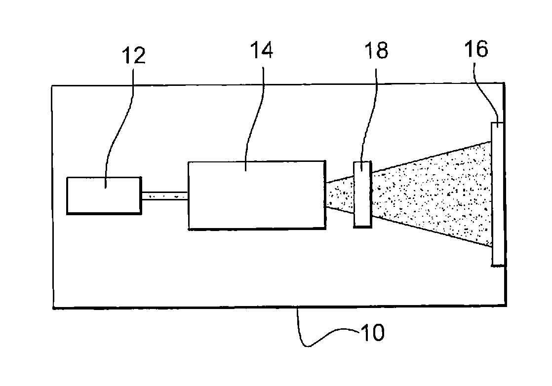
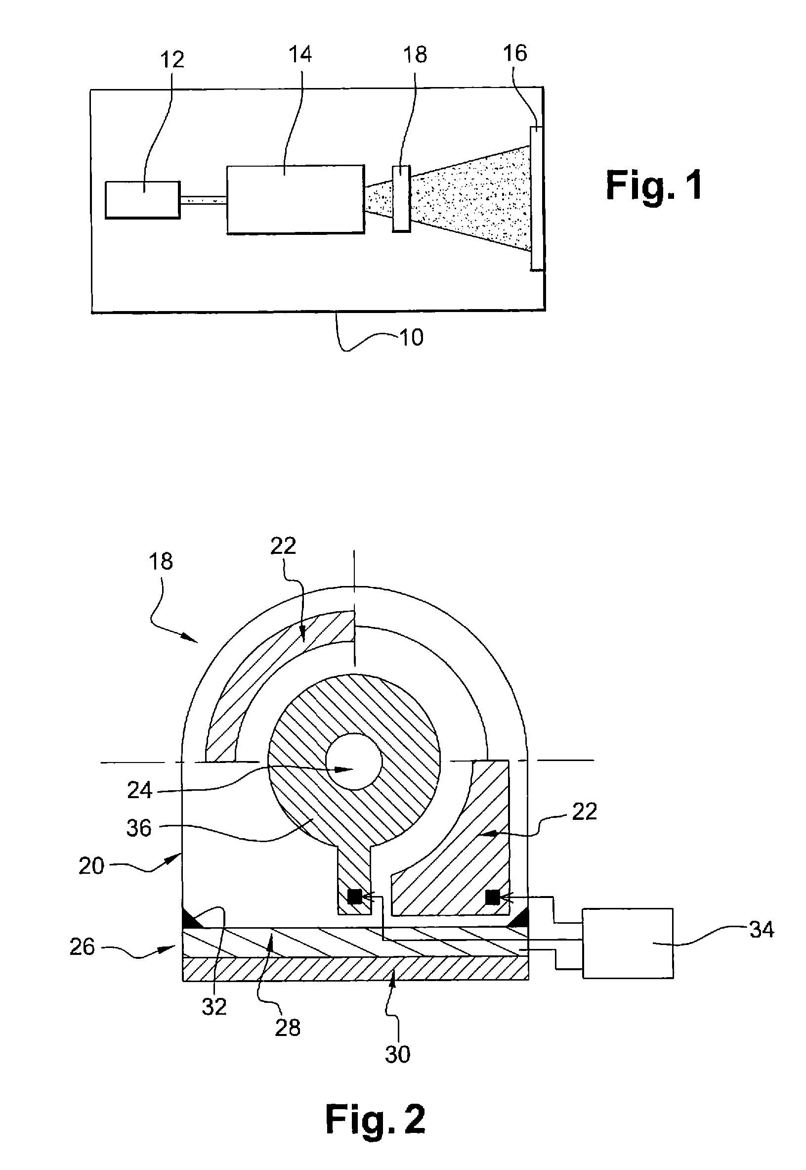
[0039]The present speckle reduction device is based on speckle reduction by a phase variation of the light rays obtained by a variation in the refractive index of an optical element through which the coherent light beam to be treated passes, the said variation being obtained by thermal perturbations caused in this optical element.

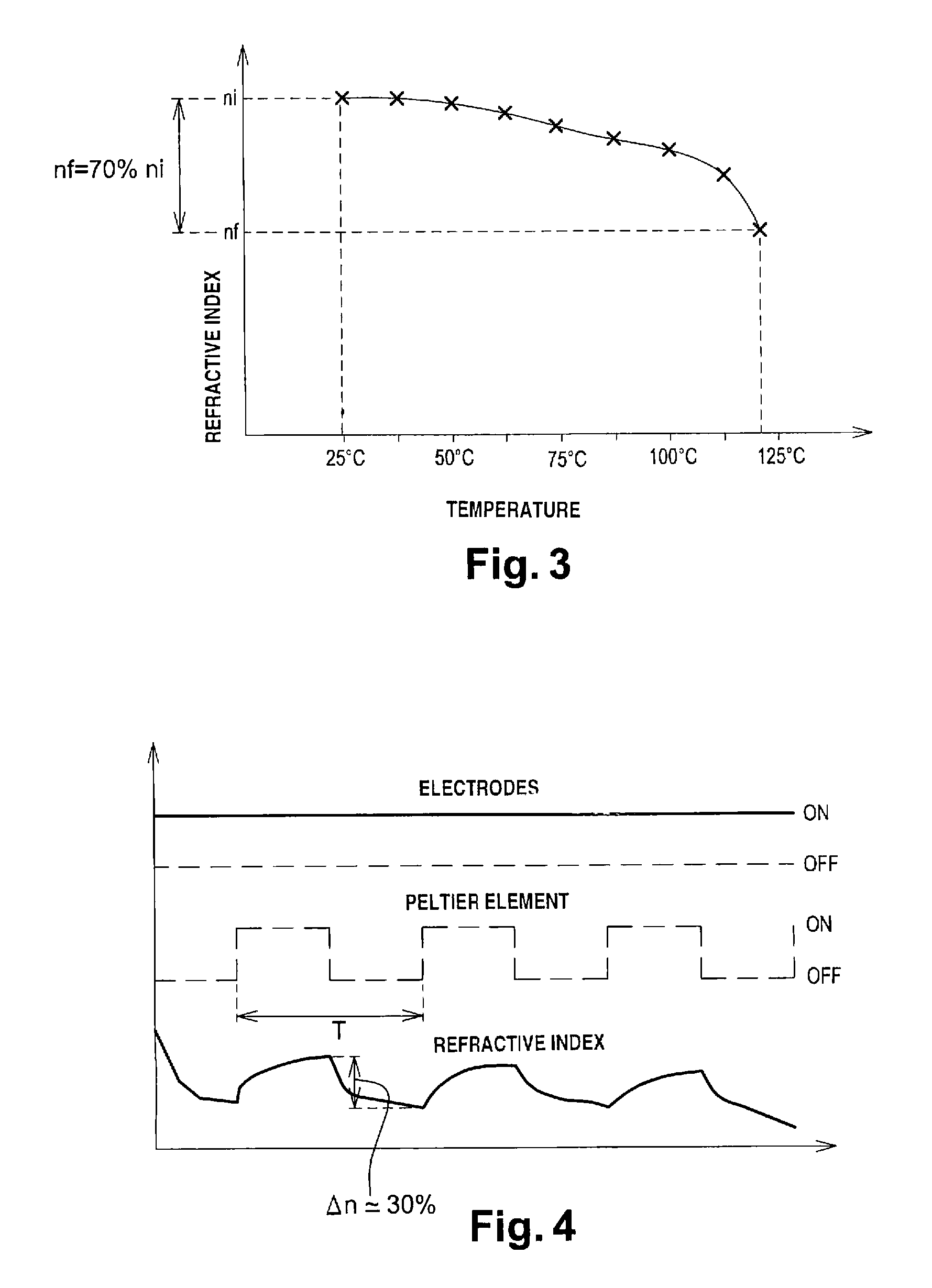
[0040]It is known that the speed of propagation (v) of a wave in a medium of refractive index n is given by the relationship: v=c / n, c being the speed of light in a vacuum. The phase velocity of a wave therefore depends on the refractive index of the medium in which this wave is propagated. It is moreover known that the refractive index of a medium depends, more or less responsively, on temperature.

[0041]The present device therefore exploits this relationship between refractive index and temperature to cause controlled phase variations in the radiation passing through it, the variations being so generated as to cause an averaging of phase in the eye of the ...


PUM

PropertyMeasurementUnit
frequencyaaaaaaaaaa
temperatureaaaaaaaaaa
sizeaaaaaaaaaa

Abstract

The present speckle reduction device comprises an optical element intended to be passed through by the coherent light beam to be treated. It also includes means able to cause heating of the said optical element; and a cooling element coupled to the said optical element so as to be able to cool the latter. A control module is configured to control the heating means and the cooling element so as to create thermal perturbations in the optical element, causing corresponding variations in the refractive index of the said optical element. The optical element is a piezoelectric crystal which is excited in a specific deformation mode causing its heating.

Description

CROSS-REFERENCE TO RELATED APPLICATION[0001]This application claims the benefit under 35 U.S.C. §371 of published PCT Patent Application Number PCT / EP 2011 / 056681, filed Apr. 27, 2011, claiming priority to French patent application number FR1053271 filed on Apr. 28, 2010, and published as WO2011 / 135008 on Nov. 3, 2011, the entire contents of which is hereby incorporated by reference herein.TECHNICAL FIELD OF INVENTION[0002]The present invention relates to a speckle reduction device and the application of this to projection units using coherent light sources, in particular of the head-up display type for motor vehicles.BACKGROUND OF INVENTION[0003]A head-up display device typically comprises a projection unit which produces a light beam intended to be directed towards a combiner for the projection of images, in particular operating information of the vehicle or more generally relating to driving in the form of a virtual image situated in the field of view of the driver.[0004]A troubl...

Claims


Application Information

Patent Timeline
Patent Type & Authority Patents(United States)
IPC IPC(8): G03B21/28G02B27/28G02B7/00G02B27/48G02F1/01
CPCG02B27/48G02B7/008G02F1/0147
Inventor MOUSSA, HASSAN
Owner APTIV TECH LTD
Learn More