Electrical cable support arrangement

a technology of support arrangement and cable, which is applied in the direction of cable installation in underground tubes, insulated conductors, cables, etc., can solve the problems of cable joint damage, subsequent service interruption, and high impact damage or breakage, and achieve the effect of convenient installation

Active Publication Date: 2015-04-30
ELECTRICAL MATERIALS
View PDF8 Cites 9 Cited by
  • Summary
  • Abstract
  • Description
  • Claims
  • Application Information

AI Technical Summary

Benefits of technology

[0006]Yet another object of the present invention is to provide support, fixed positioning, insulation and protection for power cable joint and splice arrangements in a closed environment such as a manhole.
[0007]A further object of the present invention is

Problems solved by technology

These porcelain cable saddles were very brittle and highly subject to impact damage or breakage.
However, the cotter pins were difficult to install in the steel cable supports, and thus were frequentl

Method used


Image

  • Electrical cable support arrangement
  • Electrical cable support arrangement
  • Electrical cable support arrangement

Examples


Embodiment Construction

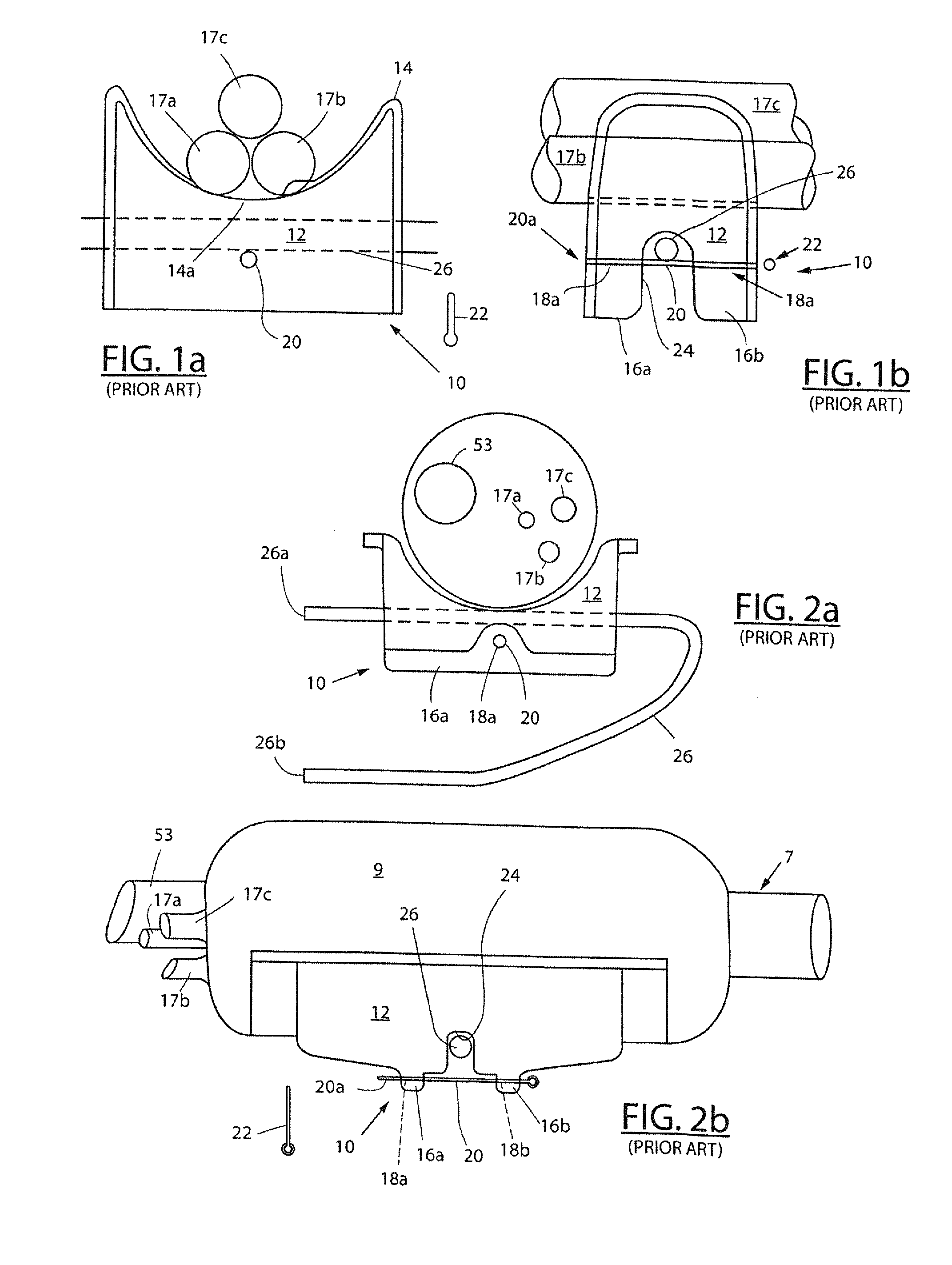
[0027]Referring to FIGS. 1a and 2b, there are respectively shown end-on and side elevation views of a prior art electrical cable saddle mount 10. FIGS. 2a and 2b are respectively end-on and side elevation views of the prior art cable saddle mount 10 illustrating additional details of the invention. Prior art cable saddle mount 10 is typically comprised of porcelain primarily for its insulating characteristics and includes a generally rectangular housing 12 having an upper portion 14 which includes a recessed portion 14a. Recessed portion 14a is generally semi-circular in shape and is adapted to receive and support one or more electrical cables, where three such cables are shown as elements 17a, 17b and 17c in FIG. 1a, with only cables 17b and 17c illustrated in FIG. 1b. The three cables form the basis for current three phase electric power distribution systems. The center axis of the cable saddle mount's recessed upper portion 14a is aligned parallel with the respective lengths of t...


PUM

PropertyMeasurementUnit
Timeaaaaaaaaaa
Lengthaaaaaaaaaa
Flexibilityaaaaaaaaaa

Abstract

An electric cable saddle, or support, arrangement includes a housing having an upper recessed portion adapted to receive and support one or more electrical cables in a fixed, stable manner. Plural apertures disposed on upper portions of the housing on opposed sides of the cable(s) and aligned generally transverse to the length of the cable(s) are adapted to receive a flexible, high strength tie member, or strap, for securely attaching the cable(s) to an upper portion of the housing. A slot disposed in a lower portion of the housing and also aligned generally transverse to the length of the cables(s) is adapted to receive a structural support member for supporting the housing and cable(s). A retaining member also disposed in a lower portion of the housing is moveable adjacent to or into engagement with the support member for fixed positioning of the housing on the support member.

Description

FIELD OF THE INVENTION[0001]This invention relates generally to the positioning and support of one or more electrical cables in a fixed, secure manner such as in an underground cable run which includes one or more manholes.BACKGROUND OF THE INVENTION[0002]Electric power cables are frequently routed underground, particularly in congested areas, using concrete enclosures, commonly known as manholes, located below grade for housing spliced cables that are continuous or form junctions for individual cable take offs. The cable junctions, or take offs, are commonly used for serving individual electric power users. In the early 1900's to on or about the year 2000, a lead sheath was installed by electrical utilities on multi-conductor power cables. This lead sheath formed part of the neutral system in multi-grounded high voltage electric power distribution systems. The lead sheath was electrically insulated from the electric cable steel supports in a manhole to prevent corrosion caused by n...

Claims


Application Information

Patent Timeline
IPC IPC(8): H02G9/06H01B3/30H01B7/00
CPCH02G9/06H01B3/30H01B7/0045H02G3/263H02G9/08H02G3/32
Inventor O'REGAN, TIMOTHY M.O'REGAN, TIMOTHY J.WOLFARD, FRANK J.O'REGAN, MICHAEL F.
Owner ELECTRICAL MATERIALS
Why Eureka
Try Eureka