
Bypassable battery modules

a battery module and bypass technology, applied in the direction of air-break switches, relays, transportation and packaging, etc., can solve the problems of failure of the series string containing the module, failure of the entire battery, permanent reduction of the battery capacity,

Active Publication Date: 2015-04-30
SAFT GRP SA
View PDF3 Cites 71 Cited by
  • Summary
  • Abstract
  • Description
  • Claims
  • Application Information

AI Technical Summary

Benefits of technology

The patent text describes a battery module and system that includes a cell stack array, solid state switches, and a solid state driver. The module and system can be controlled to operate in a complementary fashion and can be used in a battery management system. The technical effects of the invention include improved efficiency, reduced power consumption, and improved control of battery modules.

Problems solved by technology

Failure of any one module in batteries consisting of multiple series-connected modules results in the failure of the series string containing the module.
Thus, in batteries containing only one series string, the failure of one module will result in the failure of the entire battery.
However, one shot bypasses may result in permanent reduction of the battery capability while a manual module bypass is equivalent to an undesirable in-field repair or reconfiguration.
Another issue for high power batteries is that they may have sufficient power to cause failure if a very low resistance load is connected or if a short circuit occurs.
Fuses and circuit breakers have undesirable behavior in many mobile systems such as hybrid electric vehicles or aviation, where the unplanned disconnection of the battery power source from the system can cause a loss of critical function such as lighting, steering, braking, or flight control.
Further, high voltage fuses are physically large, making it difficult to incorporate them into modules.
Lithium-ion batteries in particular may have dangerously high voltage and are assembled while electrically “live” requiring operators to wear personal protective equipment.
The personal protective equipment for high voltage handling limits operator dexterity and adds significant constraints to a battery design.
However, blind mate connectors are expensive and require additional design features, such as physical interlocks to restrict operator access once any connections are engaged.
Lithium Iron Phosphate batteries with parallel branches suffer from current imbalance which can lead to uneven wear-out, or in extreme cases, overload of a branch with resistance far from the norm in either direction.
Further, uneven current sharing is self-perpetuating in that a string with lower resistance carries more current, thus dissipating more power, thus increasing its temperature, thus further lowering its resistance, which causes higher current, etc.
Electrochemical couples, such as Lithium Iron Phosphate, may be very difficult to manage due to large current imbalances between branches resulting from a large region of the OCV / SOC curve with dV / dQ≈0.
However, this process is slow and typically non-regenerative, particularly; all the energy that must be moved is dissipated in a resistance.
Additionally, such resistive precharge current limiters will fail if load capacitance is increased, for example, during integration of customer systems.
However, filter components for these DC to DC converters are large, heavy, and expensive due to the low switching frequency.
Further, using some of the above noted examples, it is impossible to increase a battery's voltage by ½ of one cell's voltage, and it is difficult to vary the voltage by less than a full module's voltage.
It is also impossible to increase a battery's capacity by less than one cell's capacity and undesirable to use cells of small capacity to tailor the capacity of a large battery.
Also, an exemplary embodiment is not required to overcome the disadvantages described above, and an exemplary embodiment may not overcome any of the problems or issues described above.

Method used


Image

  • Bypassable battery modules
  • Bypassable battery modules
  • Bypassable battery modules

Examples


Embodiment Construction

[0040]The following detailed description is provided to assist the reader in gaining a comprehensive understanding of the methods, apparatuses, and / or systems described herein. Accordingly, various changes, modifications, and equivalents of the methods, apparatuses, and / or systems described herein will be suggested to those of ordinary skill in the art. The progression of processing steps and / or operations described is an example; however, the sequence of and / or operations is not limited to that set forth herein and may be changed as is known in the art, with the exception of steps and / or operations necessarily occurring in a particular order. In addition, respective descriptions of well-known functions and constructions may be omitted for increased clarity and conciseness.

[0041]Additionally, exemplary embodiments will now be described more fully hereinafter with reference to the accompanying drawings. The exemplary embodiments may, however, be embodied in many different forms and s...


PUM


Abstract

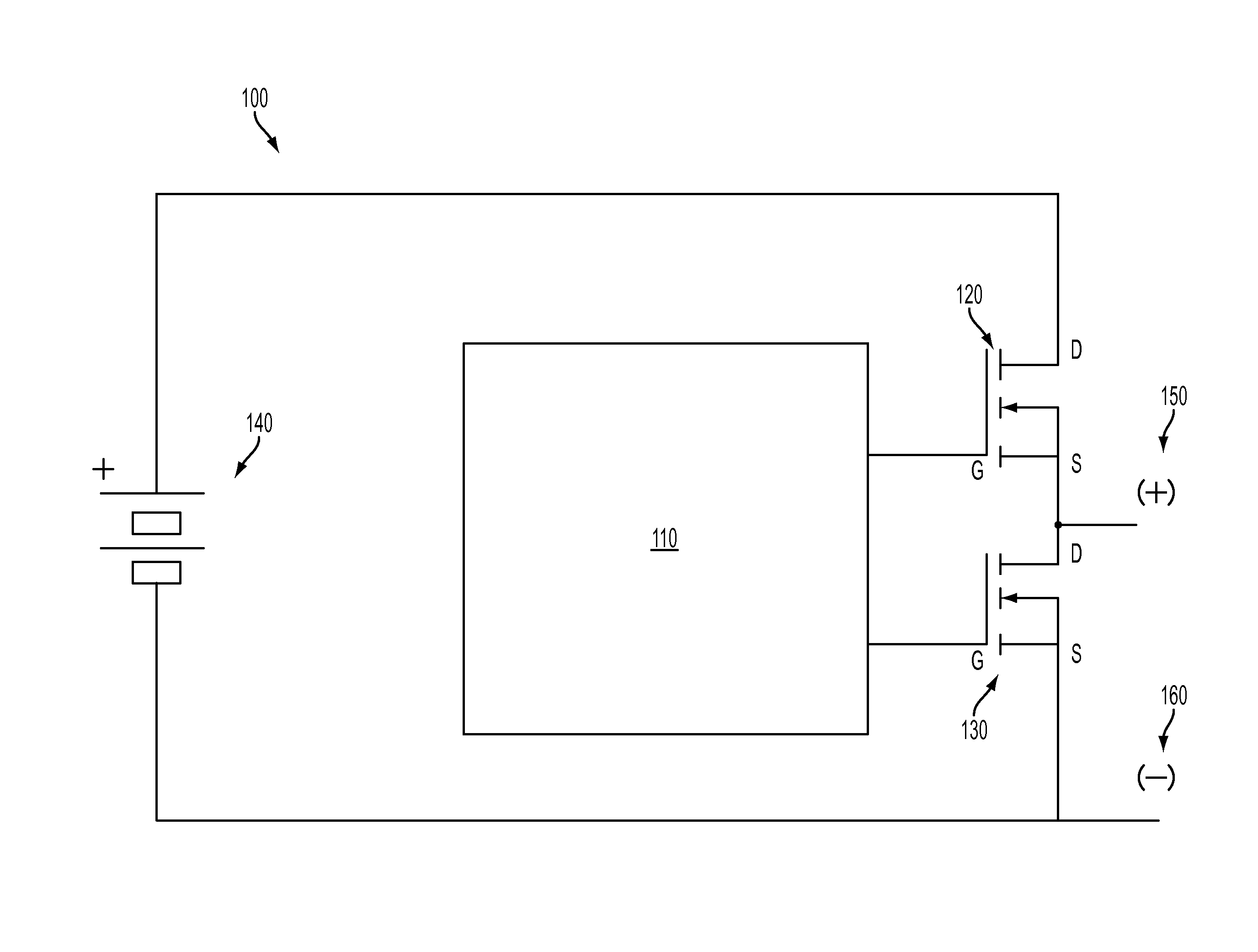
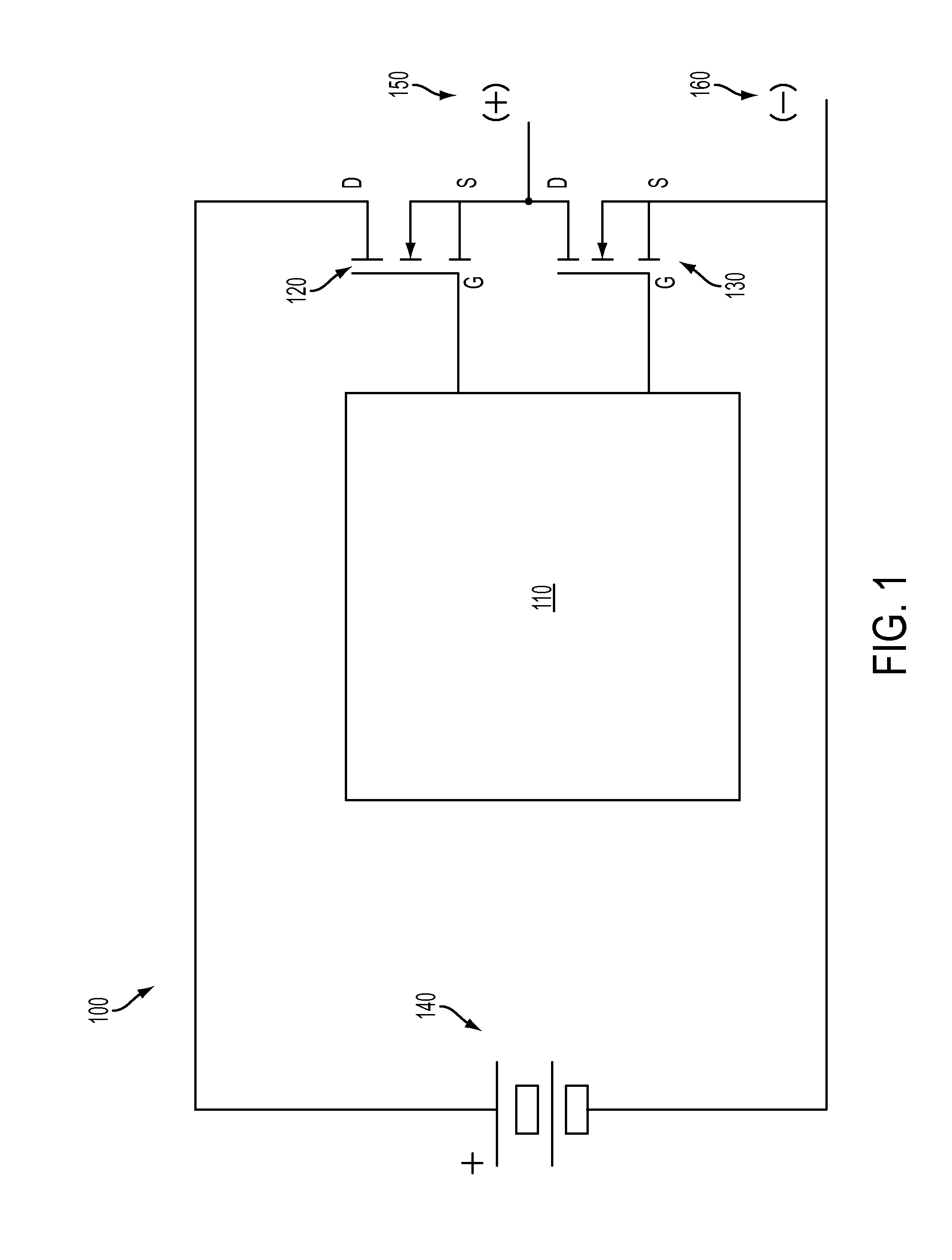
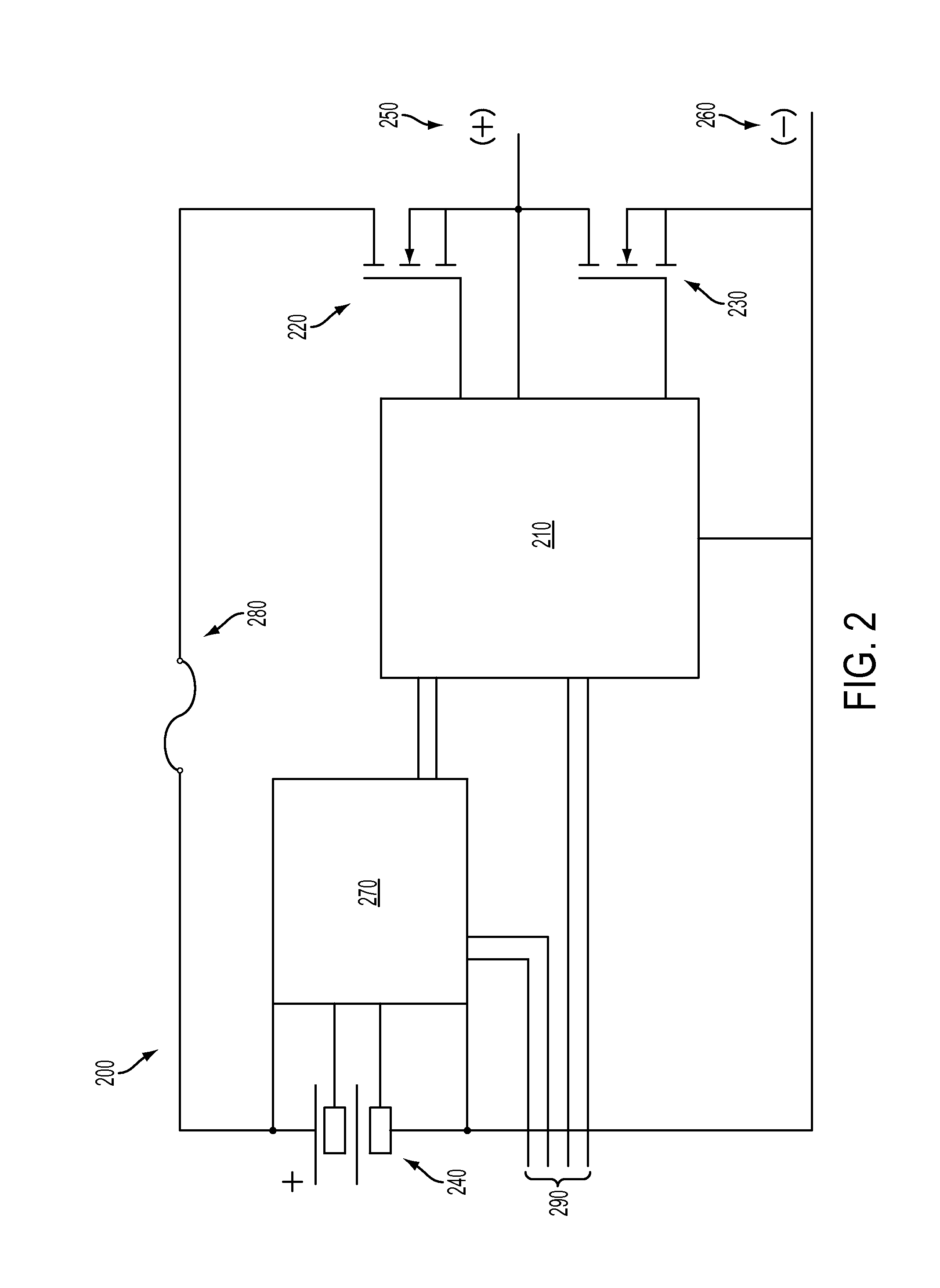
A battery system may include a plurality of battery modules connected in series. A battery module of the plurality of battery modules may include a cell stack array, a first solid state switch and a second solid state switch arranged in a half bridge configuration and configured to operate in a complementary fashion, and a solid state driver connected to both gates of the first solid state switch and second solid state switch and configured to turn on and off the first solid state switch and the second solid state switch. Further, the cell stack array is configured to be active when the first solid state switch is on and the second solid state switch is off, and configured to be bypassed when the first solid state switch is off and the second solid state switch is on.

Description

BACKGROUND[0001]1. Field[0002]Apparatuses and methods consistent with exemplary embodiments relate to a battery module and a method for controlling a battery module thereof, and more particularly, a battery module system that includes a plurality of battery modules which may each be controlled to switch from an active state to a bypassed state.[0003]2. Description of Related Art[0004]Failure of any one module in batteries consisting of multiple series-connected modules results in the failure of the series string containing the module. Thus, in batteries containing only one series string, the failure of one module will result in the failure of the entire battery. Combinations of one-shot or manual bypasses, fuses, circuit breakers, DC to DC converters, and power conditioners have been used in an attempt to mitigate the complete failure of a series string of battery modules.[0005]For example, one-shot bypasses are used at the cell level for satellite batteries, allowing the permanent ...

Claims


Application Information

Patent Timeline
IPC IPC(8): H02J1/00
CPCH02J1/00H02J7/0016H02J2207/20H02J2310/18Y02T10/70H02J7/0048
Inventor SNYDER, JAMES G.
Owner SAFT GRP SA
Learn More