Recursive de-banding filter for digital images

a filter and digital image technology, applied in image enhancement, image analysis, instruments, etc., can solve the problems of large filter size, high implementation cost, and unsatisfactory side effects of image quality

Active Publication Date: 2015-04-30
STMICROELECTRONICS INT NV
View PDF14 Cites 18 Cited by
  • Summary
  • Abstract
  • Description
  • Claims
  • Application Information

AI Technical Summary

Problems solved by technology

Conventional debanding techniques have various drawbacks, including but not limited to undesired side effects on image quality and high implementation cost.
The effectiveness of known debanding filters increases with filter kernel size, but large filters have a high implementation cost.
In some embodiments, performing error diffusion...

Method used


Image

  • Recursive de-banding filter for digital images
  • Recursive de-banding filter for digital images
  • Recursive de-banding filter for digital images

Examples


Embodiment Construction

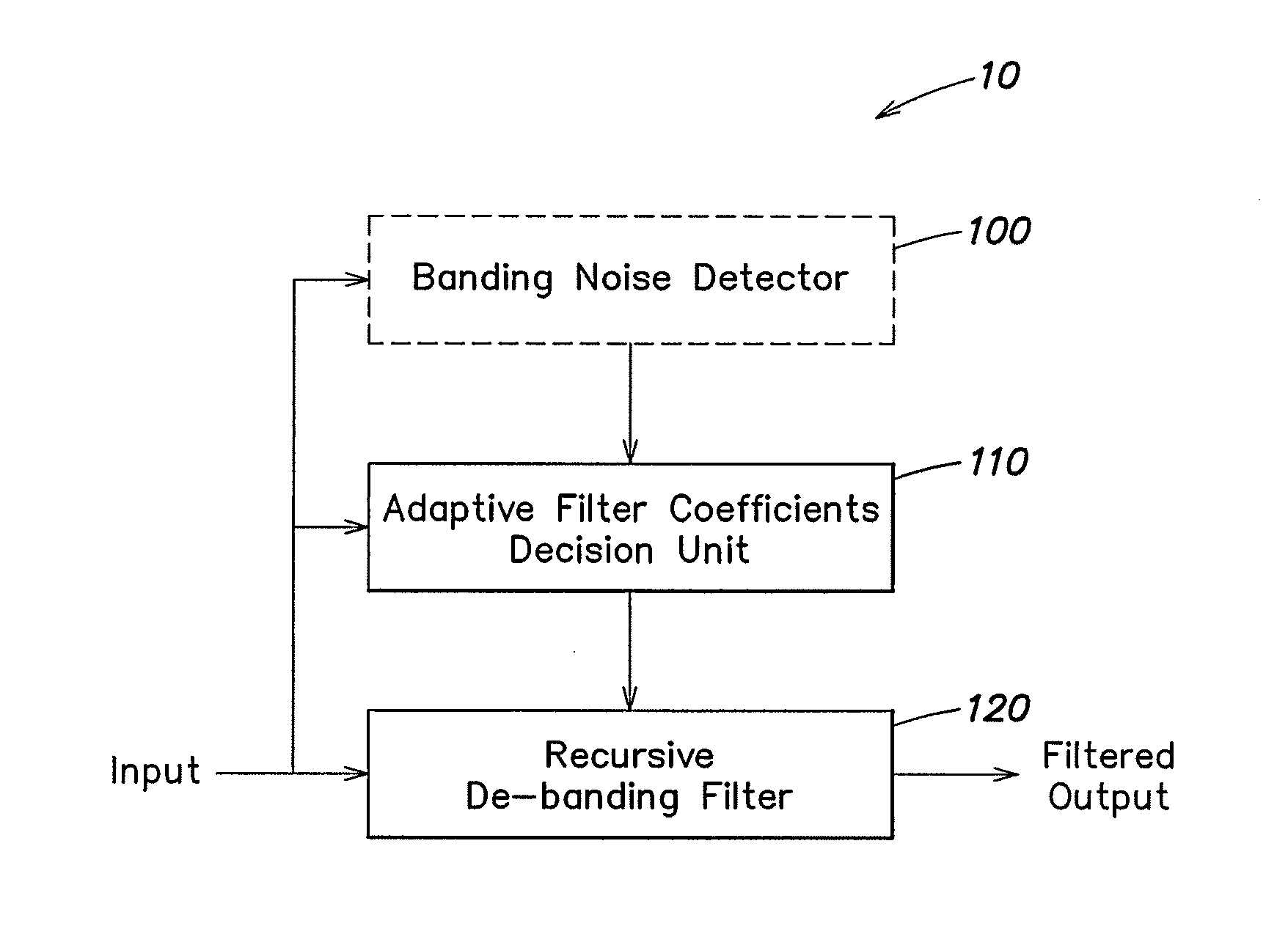
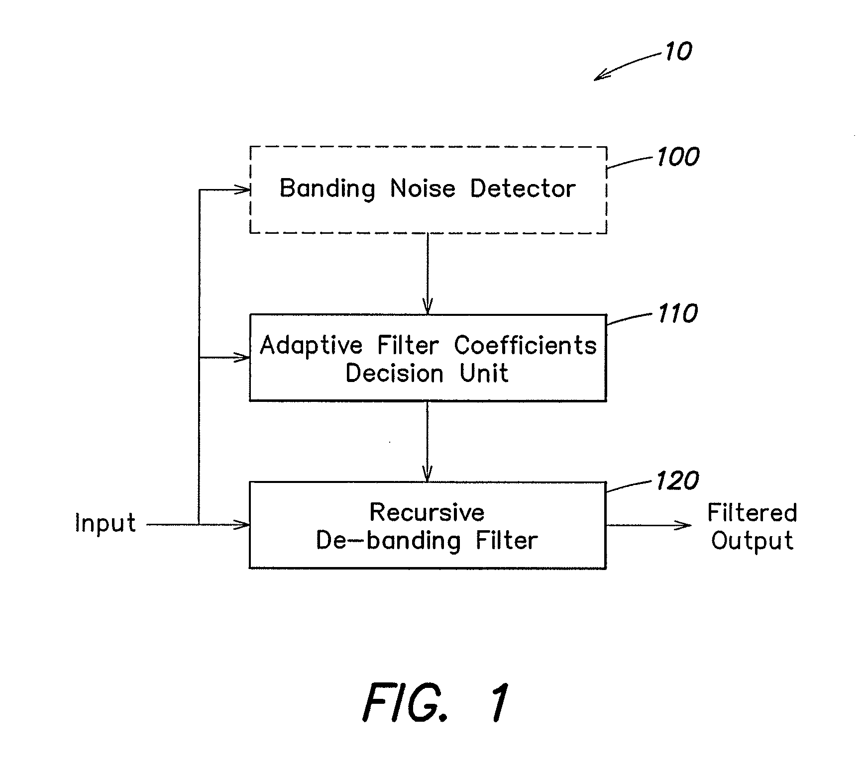
[0024]A schematic block diagram of apparatus for filtering banding noise in a digital image signal in accordance with embodiments is shown in FIG. 1 A debanding apparatus 10 receives a digital image input signal and provides a filtered output signal. The debanding apparatus 10 may be part of a set-top box or a digital television, but is not limited to these applications. The debanding apparatus 10 may be implemented, for example, in a “system-on-chip” (SOC) integrated circuit or as an application-specific integrated circuit (ASIC). In further embodiments, the debanding apparatus may be implemented as a processing device and a computer-readable storage device encoded with instructions that, when executed by the processing device, perform debanding as described herein.

[0025]Referring again to FIG. 1, a digital image input signal is provided to a banding noise detector 100, to an adaptive filter weight decision unit 110 and to a recursive debanding filter 120. The banding noise detecto...


PUM


Abstract

A method and apparatus are provided for filtering banding noise in a signal representative of an image. The method includes detecting, by a banding noise detector, banding noise in a neighborhood of a current pixel of the image, determining, by an adaptive filter weight decision unit, a number of banding steps in the neighborhood of the current pixel, determining, by the adaptive filter weight decision unit, a difference between a current pixel value and a previous output value, selecting, by the adaptive filter weight decision unit, a filter weight based on the number of banding steps, the difference between the current pixel value and the previous output value, and the detected banding noise, and filtering, by a recursive filter, the current pixel value according to the selected filter weight.

Description

BACKGROUND[0001]1. Technical Field[0002]This disclosure relates to digital video processing methods and apparatus. More particularly, the disclosure relates to image quality improvement by removal of banding artifacts, also known as banding noise.[0003]2. Discussion of the Related Art[0004]Banding artifacts, or banding noise, in a digital image or video sequence can be caused by quantization of gray scale values or color values and may appear as a false contour effect in a smooth region of the image. False contours may appear as bands in a uniform or continuously varying area of the image.[0005]Techniques have been proposed for removing banding artifacts from digital images. In one approach, a method for detecting digital contours utilizes a selected one of a plurality of search window sizes based on a corresponding variance of the image, and removes the digital contour by using a low pass filter matched to the selected search window size. Another approach utilizes a block based tex...

Claims


Application Information

Patent Timeline
IPC IPC(8): G06T5/00
CPCG06T2207/10016G06T5/002G06T5/20G06T2207/20012
Inventor DENG, XIAOYUNHUI, LUCAS
Owner STMICROELECTRONICS INT NV
Why Eureka
Try Eureka