Assembly for a prefabricated terminal block and method for producing prefabricated terminal blocks

a terminal block and assembly technology, applied in the direction of coupling device connection, transportation and packaging, coatings, etc., can solve the problems of inflexible short-term dimensional change, complex and expensive welding methods for joining plastic parts to one another, and inflexible for many applications, etc., to achieve the effect of long service li

Inactive Publication Date: 2015-04-30
ROBERT BOSCH GMBH
View PDF10 Cites 1 Cited by
  • Summary
  • Abstract
  • Description
  • Claims
  • Application Information

AI Technical Summary

Benefits of technology

[0012]A further aspect of the present invention relates to an engine control unit comprising a terminal block, wherein the terminal block can comprise an assembly that is configured as stated above and/or can have been produced in a manufacturing process as described above. The use of an inventive terminal block in an engine control unit has the advantage that through-colored plastic parts or the color scheme thereof can only be affected by large changes in temperature and the effects of weather and chemicals to a limited extent; thus preventing the electrical contacts in the pre-molded parts from being falsely...

Problems solved by technology

Injection molds in the prior art are, however, either totally inflexible with respect to short-term dimensional changes or else are extremely expensive because said molds consist of many parts and many different modules have to be made available in order to be able to form sections of a desired mold of an injection molded part.
Whereas snap-on/detent connections have tolerances that are too high or strengths that are too low for many areas of application, welding methods for joining plastic parts to be joined ...

Method used


Image

  • Assembly for a prefabricated terminal block and method for producing prefabricated terminal blocks
  • Assembly for a prefabricated terminal block and method for producing prefabricated terminal blocks
  • Assembly for a prefabricated terminal block and method for producing prefabricated terminal blocks

Examples


Embodiment Construction

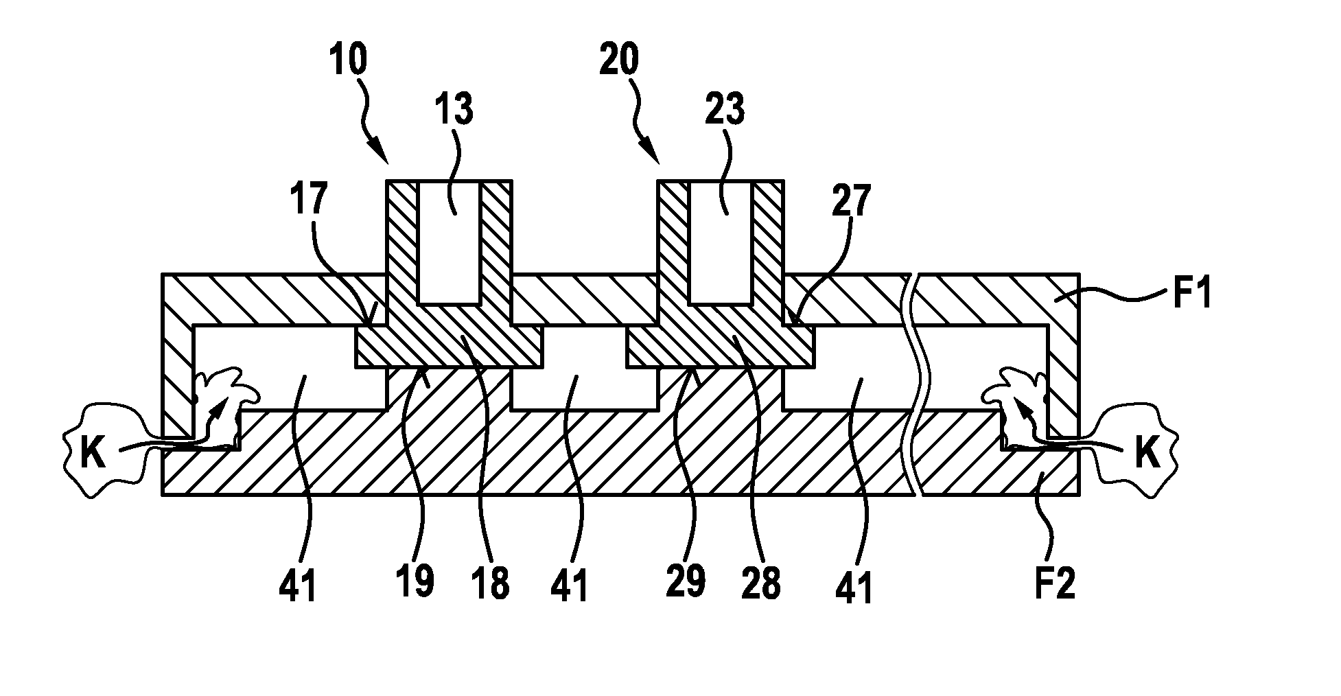
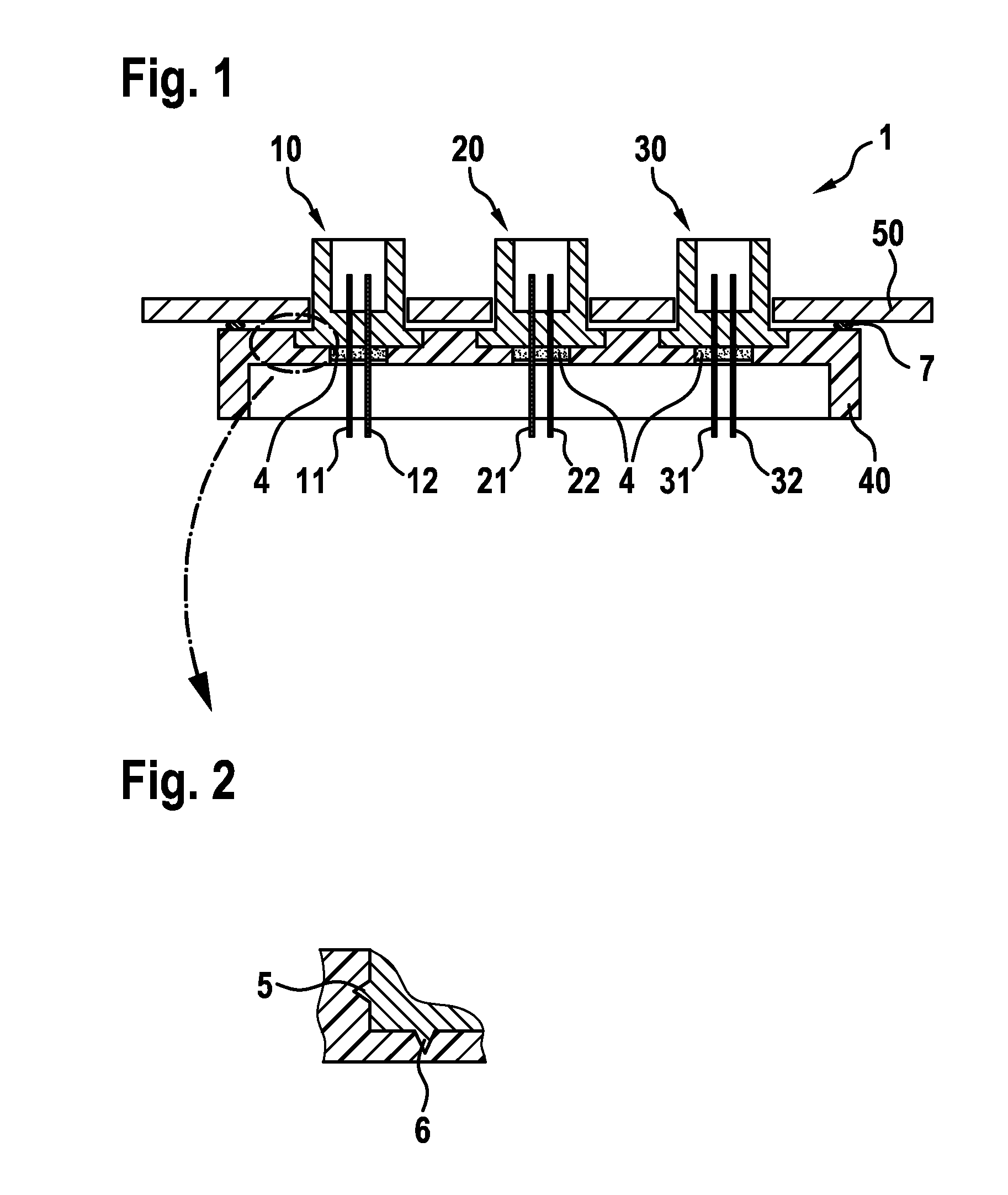
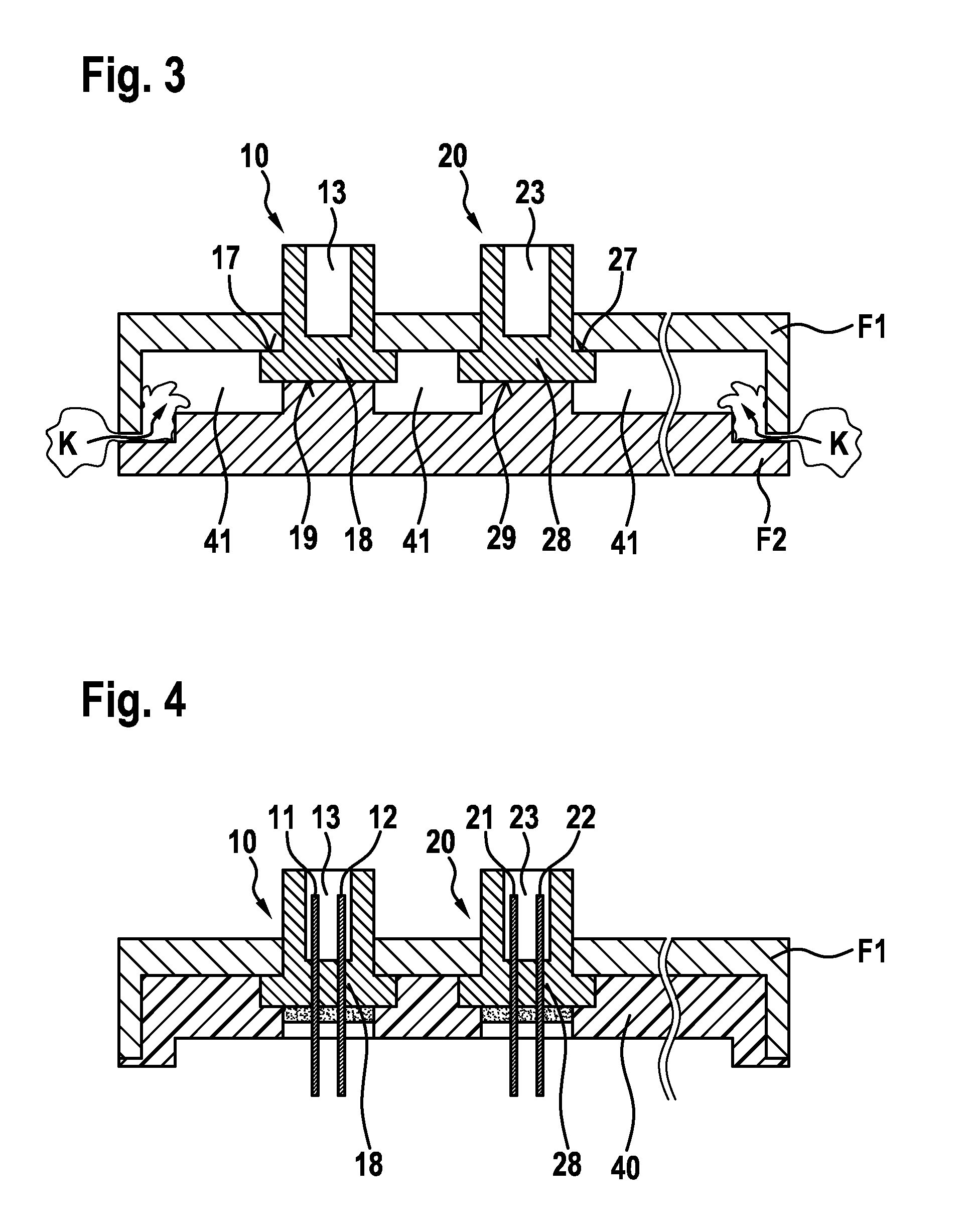
[0019]FIG. 1 shows a cross-sectional view through an exemplary embodiment of a prefabricated terminal block 1 according to the invention. The terminal block 1 comprises three pre-molded parts 10, 20, 30, which penetrate openings in a housing 50 of an engine control unit (ECU). The pre-molded parts 10, 20, 30 are held together on the back sides thereof by a base frame 40. Electrical contacts 11, 12, 21, 22, 31 and 32 penetrate in each case in pairs (e.g. in single or multiple rows) the pre-molded parts 10, 20, 30 as well as a gel injection which is provided at the back in the region of the electrical contacts 11, 12, 21, 22, 31 and 32 and is disposed in a region of the base frame 40 without injection molding material. A seal 7 extending circumferentially around the pre-molded parts 10, 20, 30 is provided between the housing 50 of the engine control unit and the front of the base frame 40, said seal being applied under preload between the housing 50 and the base frame 40. The pre-mold...


PUM


Abstract

The invention relates to an assembly for a prefabricated terminal block and to a method for producing a prefabricated terminal block, wherein two pre-moulded parts are held together by an injection-moulded base frame. The pre-moulded parts can be designed to provide electrical contacts for contacting an engine control unit for example, in order to establish electrical connections to the engine control unit. In particular, prefabricated parts for terminal blocks that are flexible with respect to material and colouring can be implemented in this way.

Description

BACKGROUND OF THE INVENTION[0001]The manufacture of terminal blocks, in particular for use in the automotive field, by means of plastic injection molding technology is known in the prior art. Injection molds in the prior art are, however, either totally inflexible with respect to short-term dimensional changes or else are extremely expensive because said molds consist of many parts and many different modules have to be made available in order to be able to form sections of a desired mold of an injection molded part. Components which have to be flexibly adapted with respect to shape and coloring are often individually manufactured and are later joined to one another by means of snap-on / detent connections or else in a materially bonded manner by known welding or adhesive bonding techniques. Whereas snap-on / detent connections have tolerances that are too high or strengths that are too low for many areas of application, welding methods for joining plastic parts to be joined to one anoth...

Claims


Application Information

Patent Timeline
IPC IPC(8): H01R9/24B60R16/023H01R9/22H01R43/18
CPCH01R9/24H01R9/223B60R16/023H01R43/18B29C45/14467B29C45/14639
Inventor FRIESS, GERALD
Owner ROBERT BOSCH GMBH
Why Eureka
Try Eureka